¶ 2D Plane Programming
This tutorial explains the method of 2D path programming in Kiri.moto.
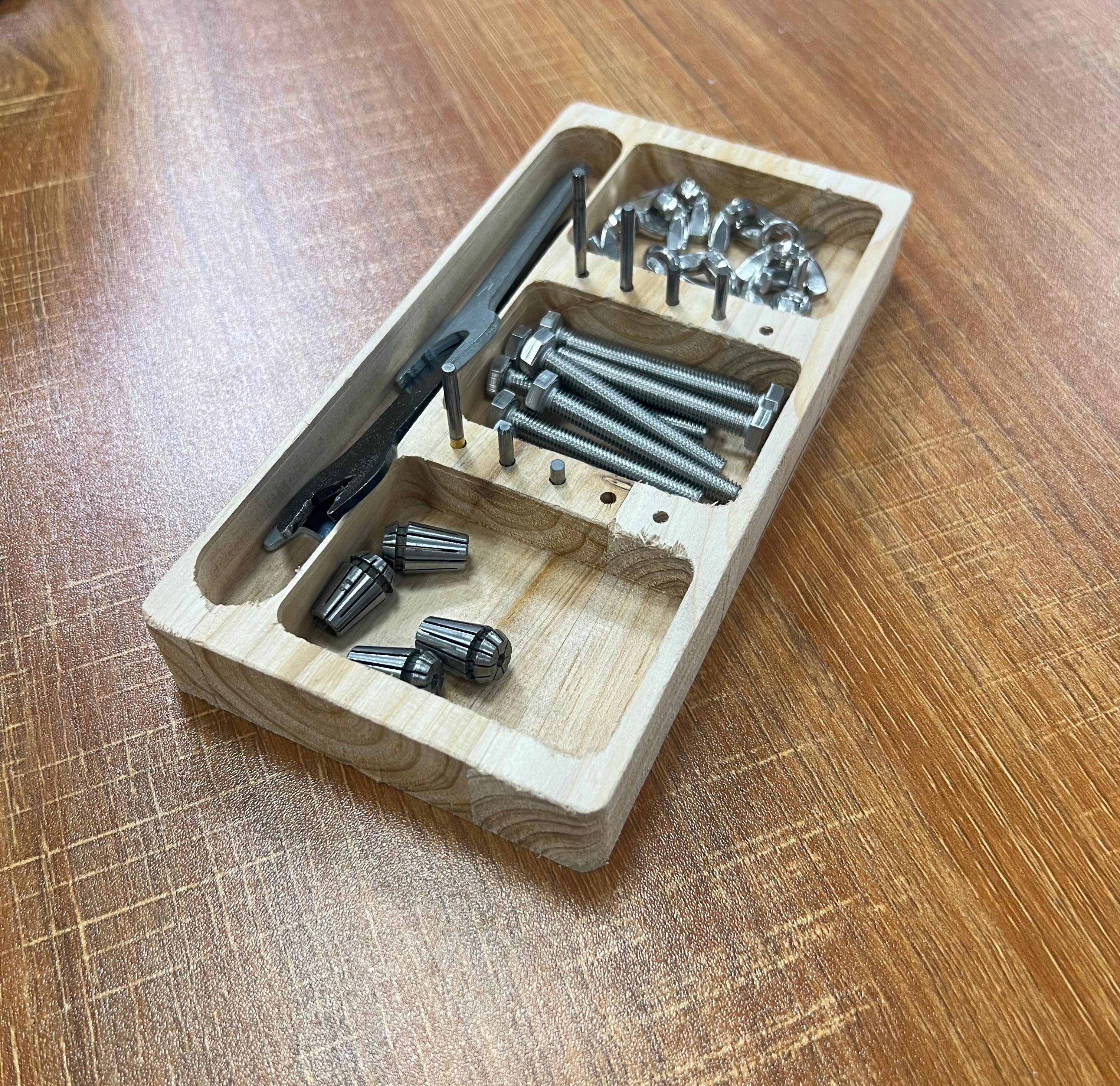
Case demonstration: Taking the tool box production process as an example, it covers applications such as drilling, slotting and contour cutting.
Example diagram:
|
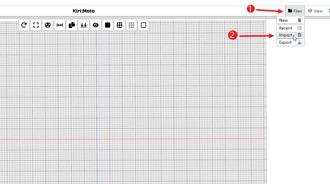
Step 1
Perform the operations according to the sequence numbers.
- 1.Click on the file
- 2.Import the prepared files
|
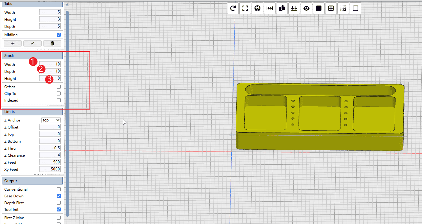
Step 2
Perform the operations according to the sequence numbers.
- 1.Set the reserve quantity of the X-axis inventory (calculated based on the size of the sheet material and the model, and a space for fixing the plywood needs to be reserved)
- 2.Set the reserve quantity of the Y-axis inventory (calculated based on the size of the sheet material and the model, and a space for fixing the plywood needs to be reserved)
- 3.Set the remaining inventory after setting Z (if the model and the thickness of the sheet are the same, set it to 0)
|
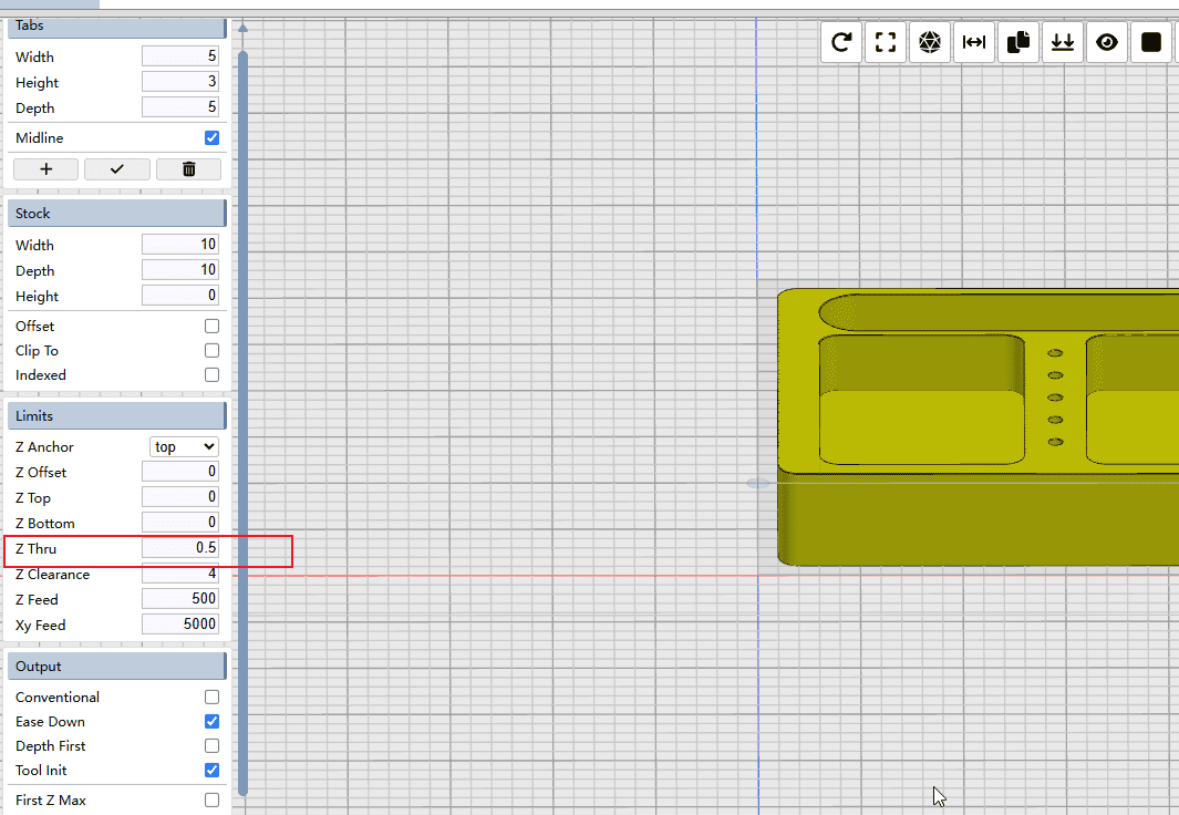
Step 3
If cutting is required, it is recommended to place some sacrificial materials at the bottom. Set the Z-Thru value to 0.5, allowing the tool to make a slight overcut along the Z-axis to ensure a complete cut.
|
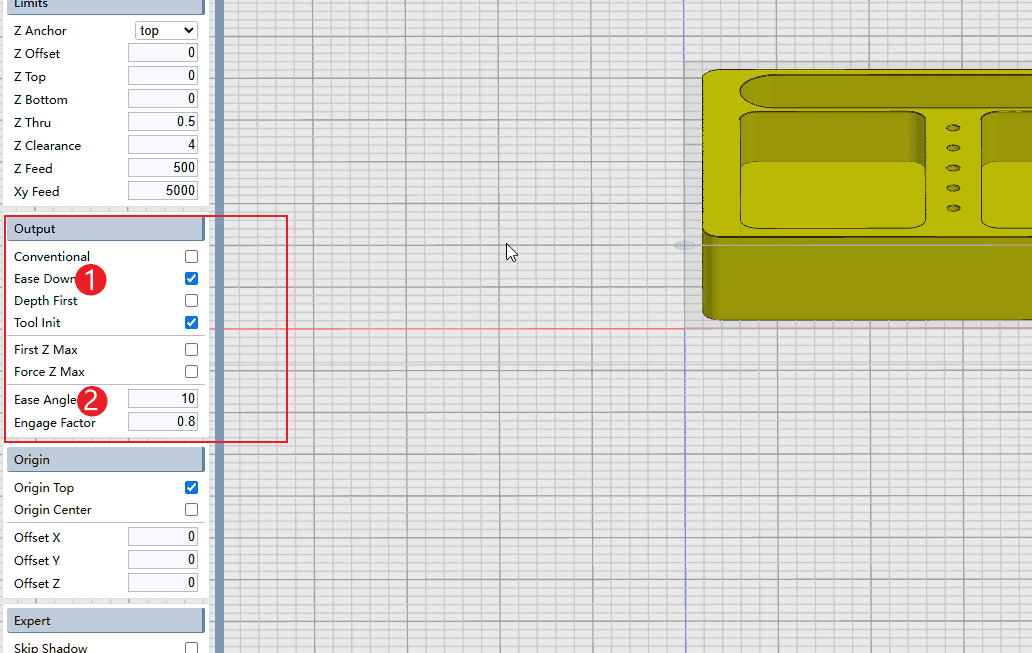
Step 4
Perform the operations according to the sequence numbers.
- 1.Check the “Layered Chopping” mode, and select the gentle option (when performing layer-by-layer chopping, enter the material in a slanted manner)
- 2.Set the easing angle to 10 (which means entering the material at a 10-degree angle when changing layers)
|
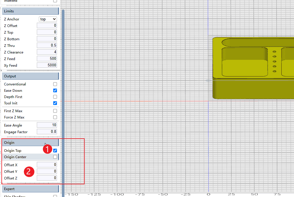
Step 5
Perform the operations according to the sequence numbers.
- 1.Set the origin at the lower left corner.
- 2.The offset of the origin can be set according to the requirements (generally, setting it to 0 is sufficient as the default value).
|
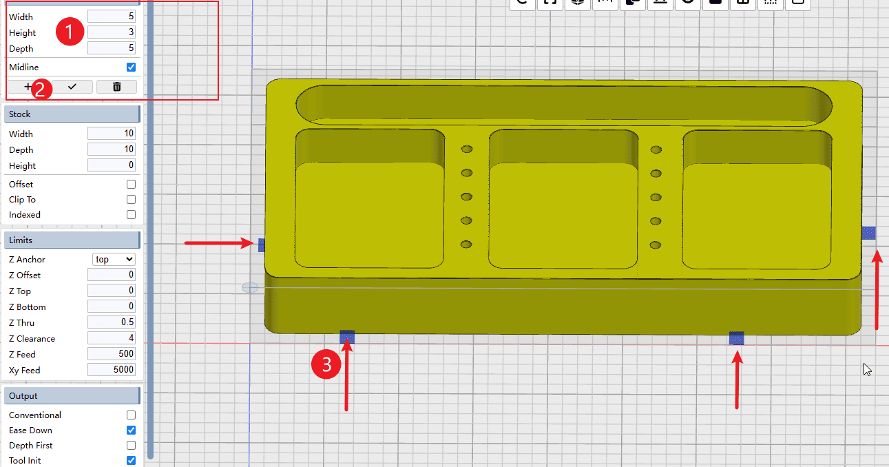
Step 6
Perform the operations according to the sequence numbers.
- 1.Set the parameters of the bridge
- 2.Click the plus sign to start adding.
- 3.Clicking on the side of the model will automatically generate a bridge (you can add as many as needed).
|
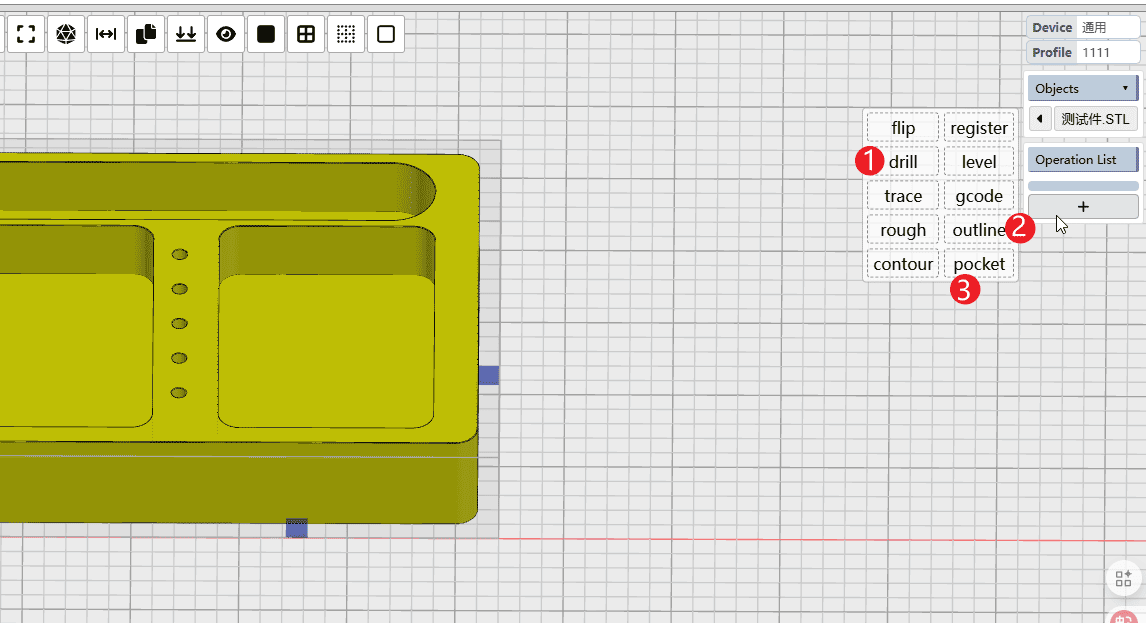
Step 7
Perform the operations according to the sequence numbers.
- 1.Click the “+” button to start adding the cutting path, and select the drilling operation.
- 2.Add cutting path
- 3.Add slotting and hollowing cutting path
|
Step 8
When the mouse hovers over the drilling instruction, start setting the drilling process. Proceed with the operation according to the sequence numbers.
- 1.Select the knife that needs to be used
- 2.Set feed rate (Note: It needs to be converted according to the current speed of the machine. Do not simply apply the value directly.)
- 3.Set the depth of each cut-down operation
- 4.Set the stay time to 0
- 5.Set the height at which the drill bit rises after each cut (this can be adjusted according to your needs)
- 6.Check the top of the listed inventory materials
- 7.Click to select the features that need to be drilled on the model.

|
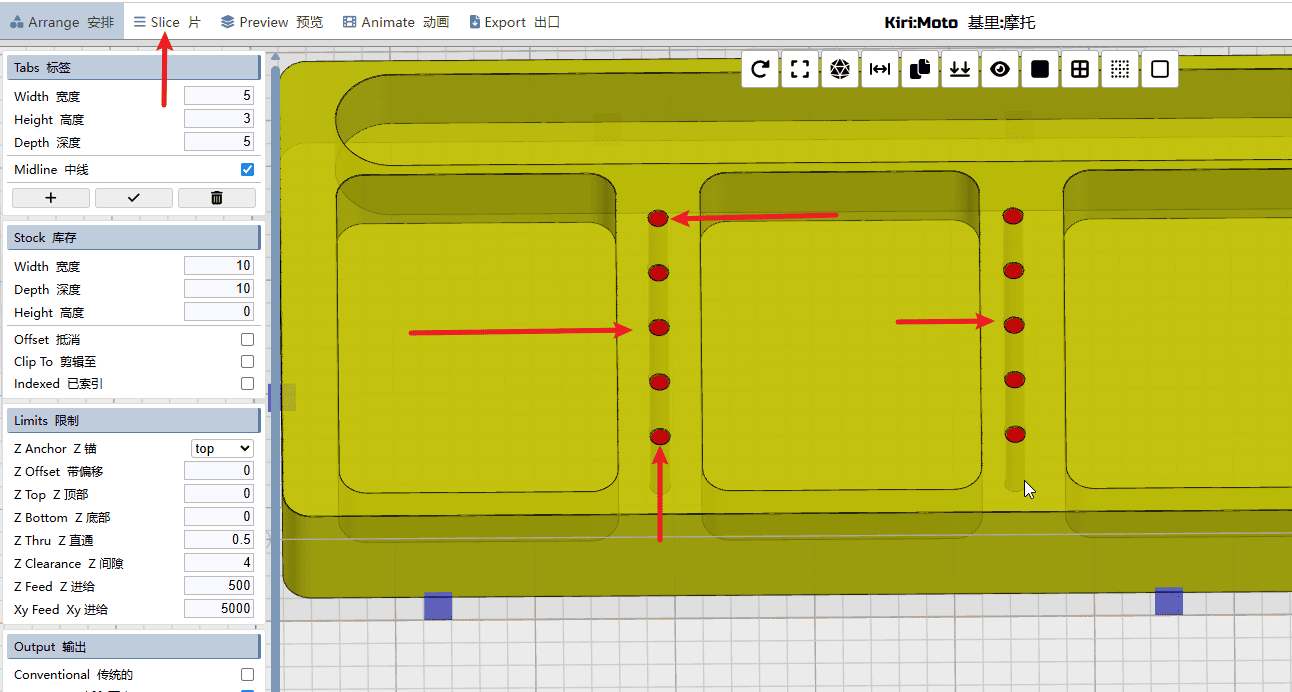
Step 9
Click on the features with holes on the model (the ones shown in red indicate selection), and then click the top left corner of the slice to calculate the drilling path.
|
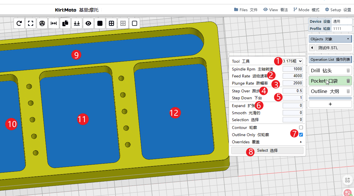
Step 10
When the mouse hovers over the slot-cutting instruction, start setting the cutting path and operate according to the sequence numbers.
- 1.Select the tools that need to be used
- 2.Set the feed rate for X and Y axes (Note: It needs to be converted according to the current speed of the machine. Do not simply apply the value directly.)
- 3.Set the undercut rate of Z (
Note: It needs to be converted according to the speed of the existing machine. Do not simply apply the value directly) - 4.Set the travel distance for each cut (keep it below the tool radius)
- 5.Set the depth of each layer’s undercut
- 6.Expansion is not mandatory here. It is only necessary to expand the diameter of the tool when it is needed to create an open slot, in order to prevent interference during the cutting process.
- 7.Check “Only Outline”
- 8.Click to select the position where the slot needs to be made.
- 9-12.Just click on each feature in sequence to select them.
|
步骤11
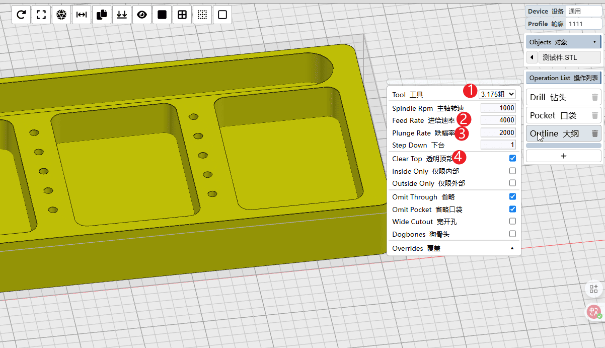
When the mouse hovers over the cutting instruction, you can edit the cutting path. Operate according to the sequence numbers.
- 1.Select the tools that need to be used
- 2.Set the feed rate for X and Y axes (Note: It needs to be converted according to the current speed of the machine. Do not simply apply the value directly.)
- 3.Set the undercut rate of Z (
Note: It needs to be converted according to the speed of the existing machine. Do not simply apply the value directly) - 4.Set the depth of the undercut.
|
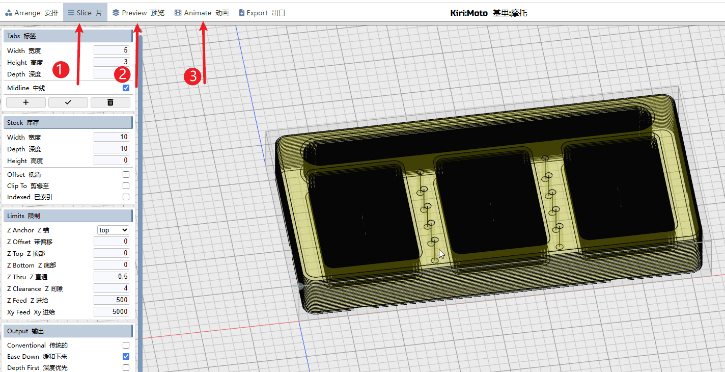
Step 12
Perform the operations according to the sequence numbers.
- 1.Click on the slice and wait for it to complete.
- 2.Click to preview. The black lines in the picture represent the path of the tool.
- 3.Click on simulation to prepare for the simulation of the cutting path. Click on simulation to prepare for the simulation of the cutting path.
|
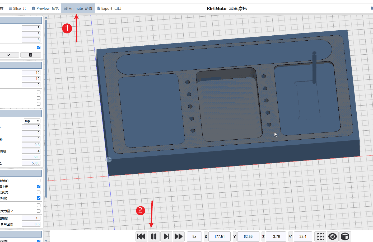
Step 13
Perform the operations according to the sequence numbers.
- 1.Click on the simulation to enter the simulation page.
- 2.Click the play button to watch the simulated battle path.
|
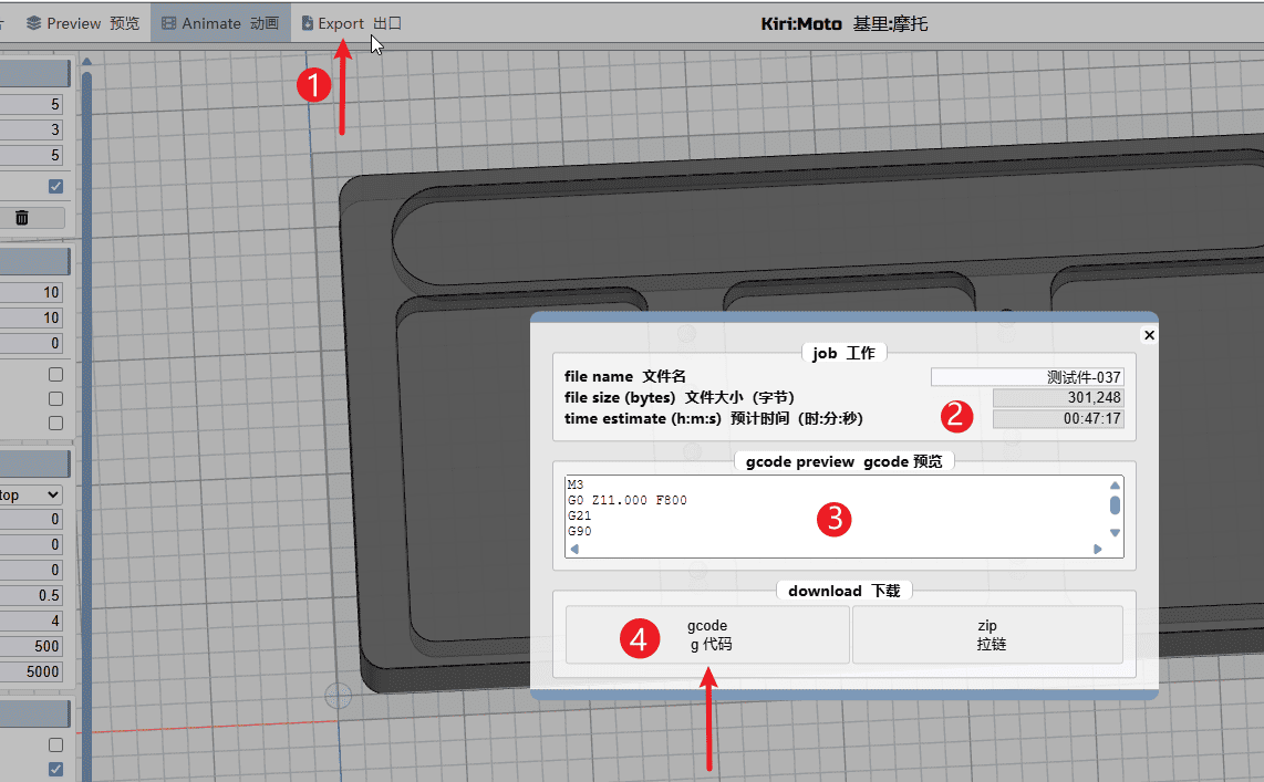
Step 14
Perform the operations according to the sequence numbers.
- 1.Click “Export”
- 2.Naming the programming files
- 3.You can drag the progress bar here to preview the G-code.
- 4.Click on the “G code export” option to proceed.
Attention! Attention! Attention!!!!!!!!!!!!!!
Multiple machining paths for the same tool: As shown in the tutorial, multiple processing paths using the same tool can be combined and output to a single NC file.
Different tool paths for different tools: If the model processing requires the use of different tools, then the tool paths corresponding to each tool must be saved separately and output as individual NC files to avoid processing accidents caused by incorrect tool changes.
|