¶ 2D-programming
This tutorial explains the methods for implementing 2D machining programming in Fusion 360.
Source of the document: You can directly create the required graphics in the software design workspace, or you can import external design files (it is recommended to use the STEP format (.stp) to ensure the complete conversion of geometric data)
This demonstration will require the use of common commands such as slotting, drilling, and contour cutting.
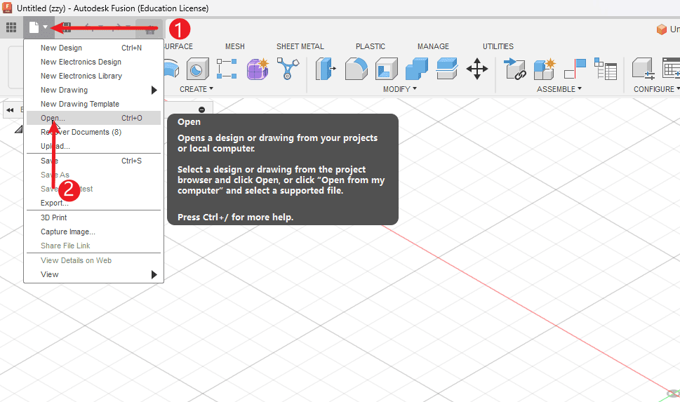
Step 1
Perform the operations according to the sequence numbers.
- 1.Click on the file
- 2.Click to open the file
|
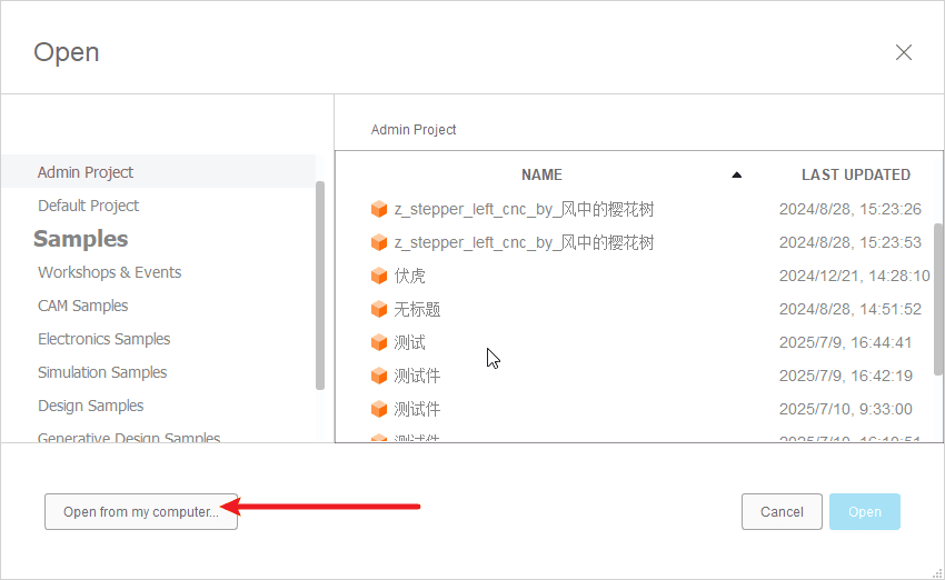
Step 2
- Click to open the folder
|
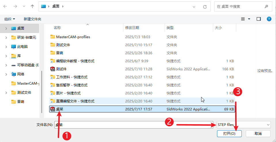
Step 3
- 1.Select file
- 2.Pay attention to the format of the document.
- 3.Click to open
|
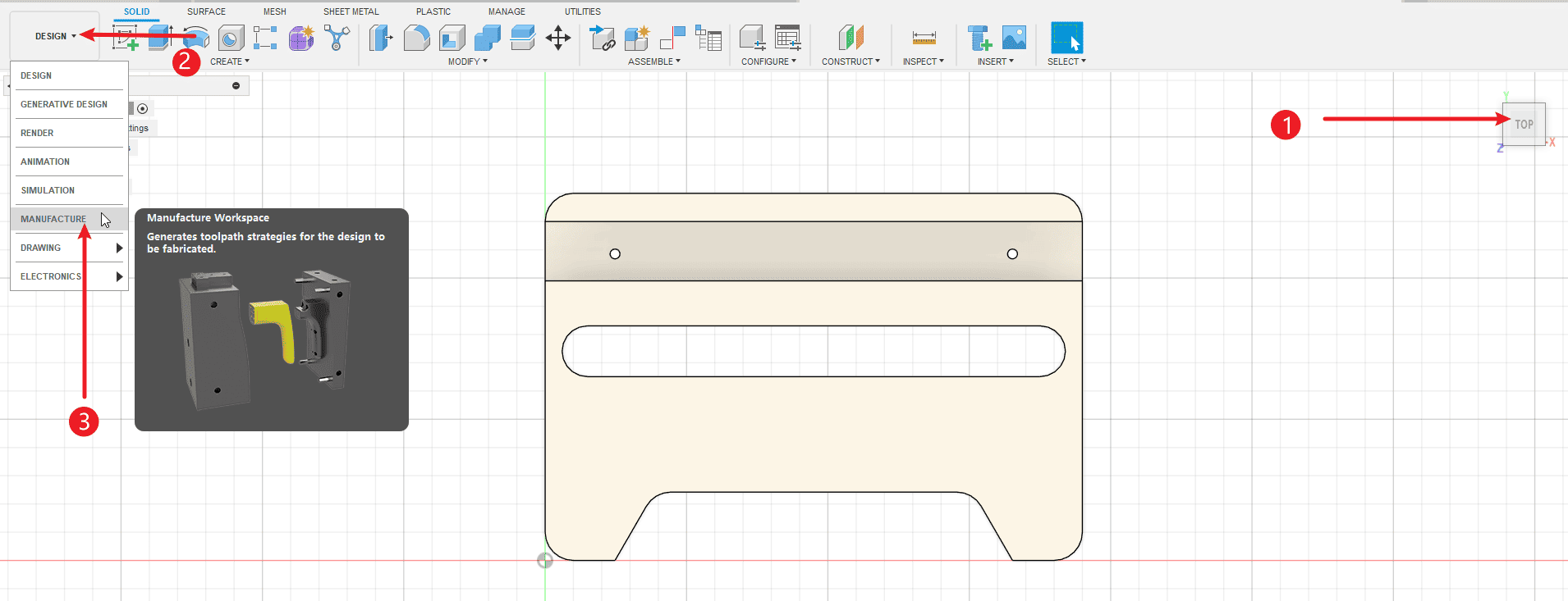
Step 4
Perform the operations according to the sequence numbers.
- 1.Click on the “View” option
- 2.Click on the workbench
- 3.Switch to the CAM workbench
|
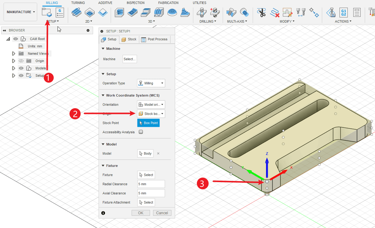
Step 5
Perform the operations according to the sequence numbers.
- 1.Click “New Settings” to create a working environment.
- 2.Set the origin as the boundary box point
- 3.Click on the point you want to set as the origin for the operation.
|
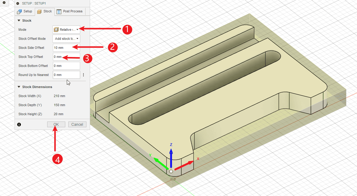
Step 6
Perform the operations according to the sequence numbers.
- 1.Switch to the rough casting settings. You can choose either a fixed-size rough casting or a relative-sized one.
- 2.Set the offset of the rough casting, the side represents the offset of XY, the offset needs to be set relative to the rough casting. For fixed size, the size of the sheet material will be output.
- 3.The offset of Z is set to 0 if the thickness of the sheet material is the same as that of the model.
- 4.Click “OK” to complete the creation of the environment.
|
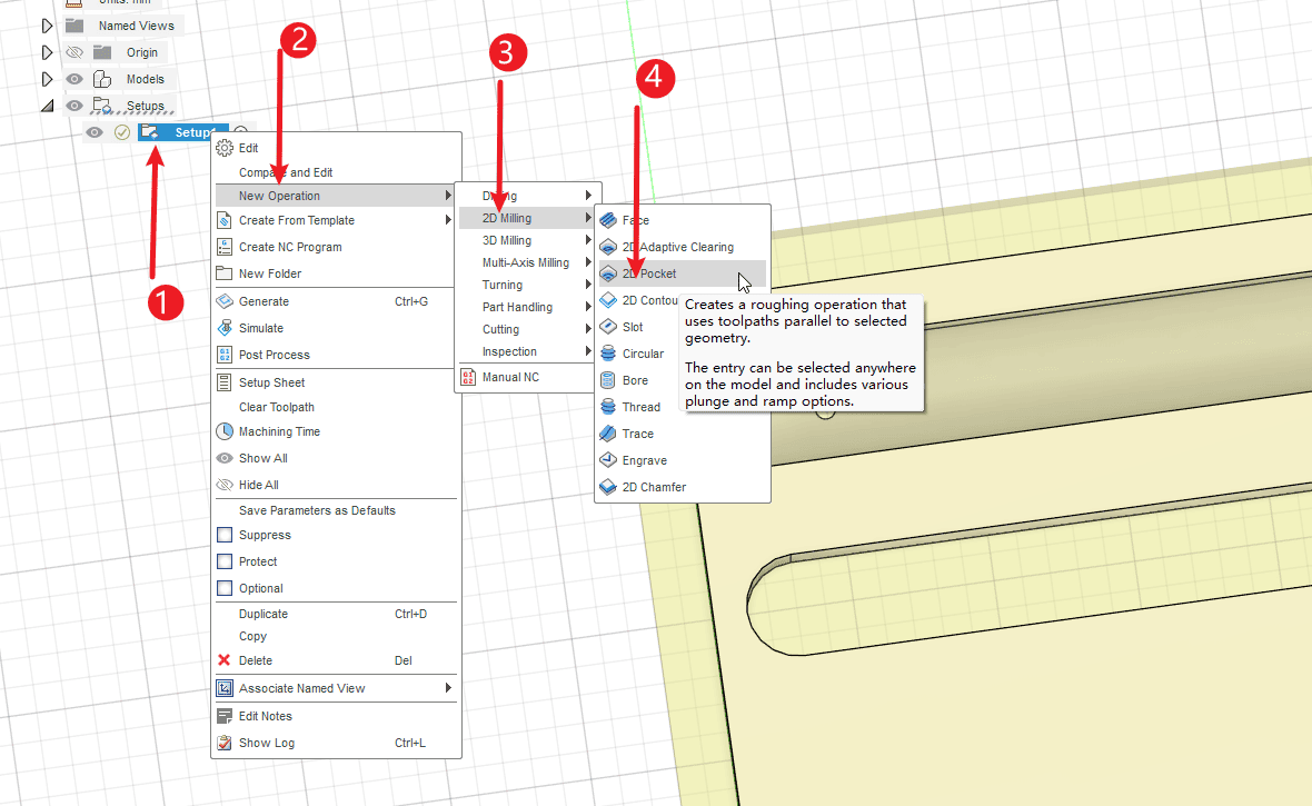
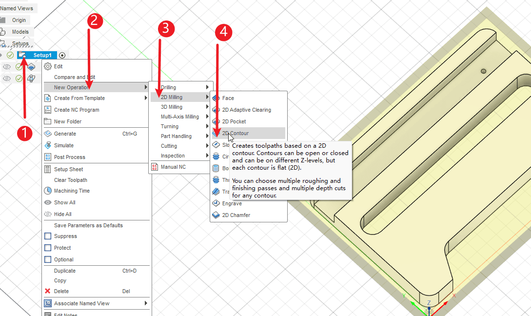
Step 7
Perform the operations according to the sequence numbers.
- 1.Right-click to create the already established environment
- 2.Select the “New” operation
- 3.Select 2D operation
- 4.Select the 2D slotting command
|
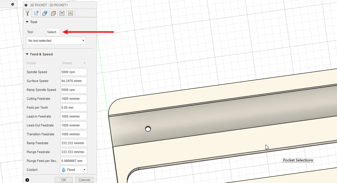
Step 8
- Choose a knife that you will use
|
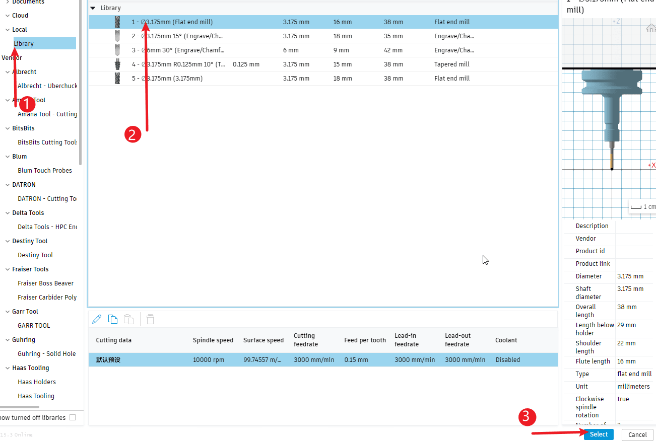
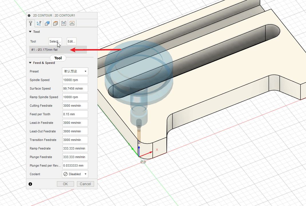
Step 9
Perform the operations according to the sequence numbers.
- 1.Click on the local area
- 2.Select the previously added cutting tools
- 3.Click to use
|
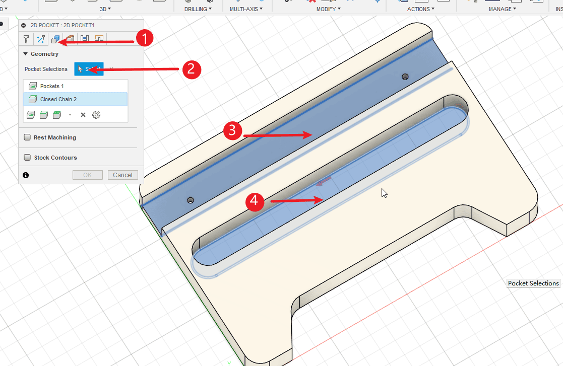
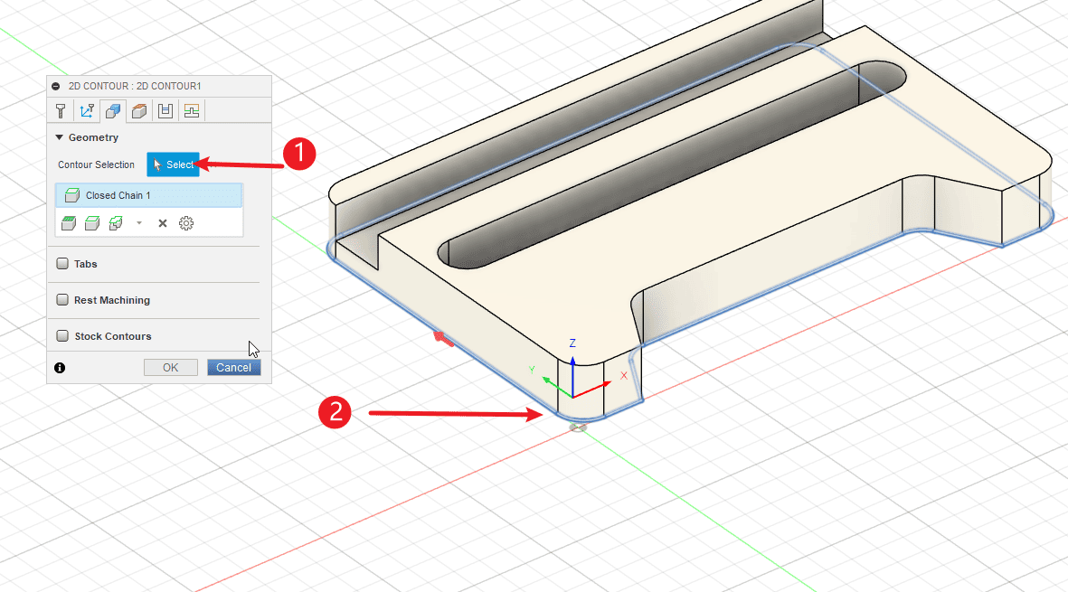
Step 10
Perform the operations according to the sequence numbers.
- 1.Click on the shape
- 2.Click to select
- 3-4.Click on the surface that needs to be hollowed out
|
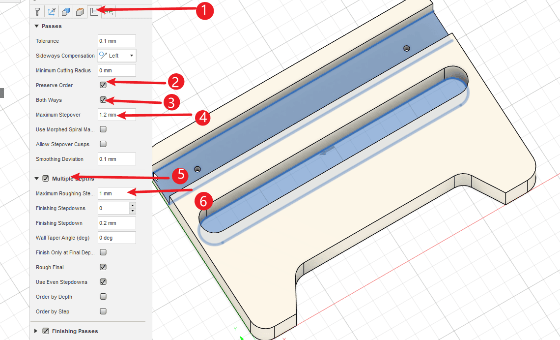
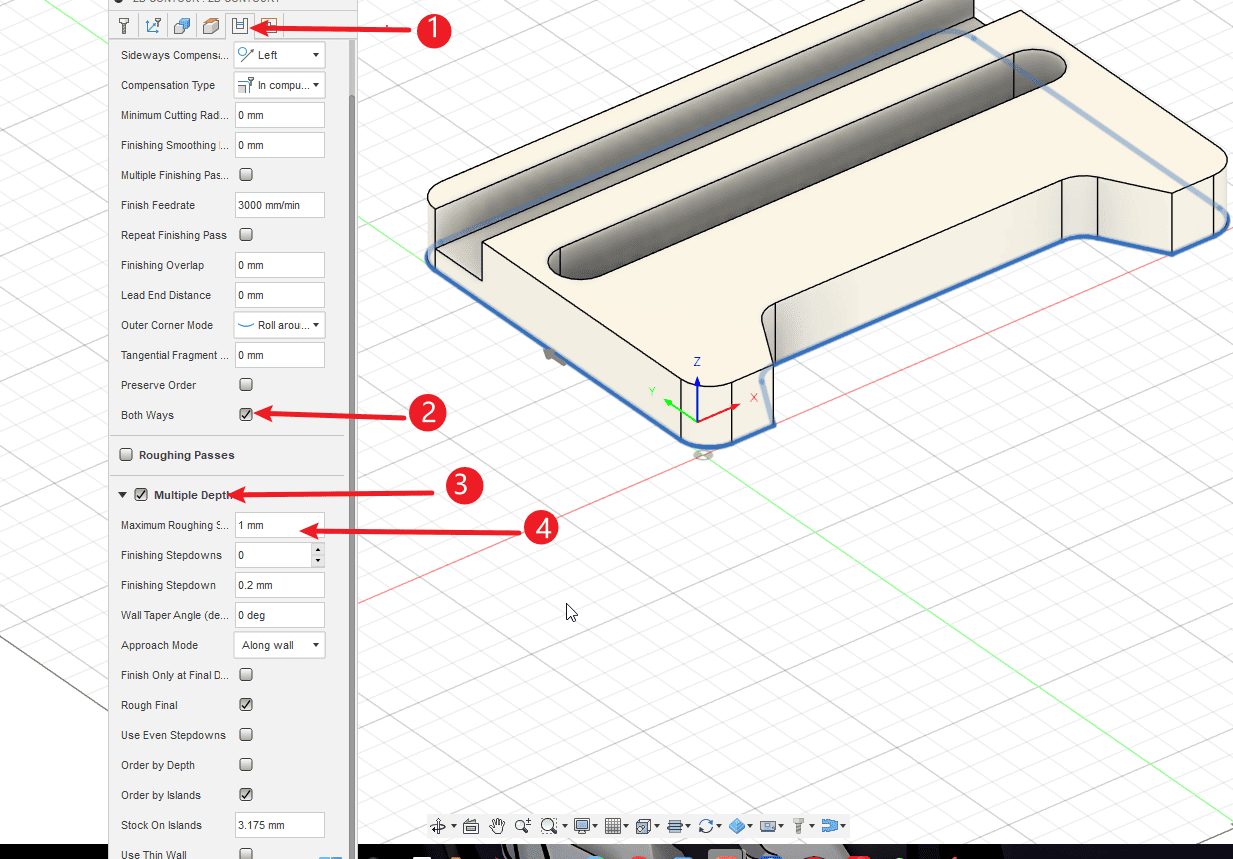
Step 11
Perform the operations according to the sequence numbers.
- 1.Click on the processing path
- 2.Check “Keep Order”
- 3.Check the option for bidirectional cutting path
- 4.Set the feed rate. Usually, the default value is the feed rate in the tool settings.
- 5.Select layered milling
- 6.Set the depth of each cut for the layered milling operation
|
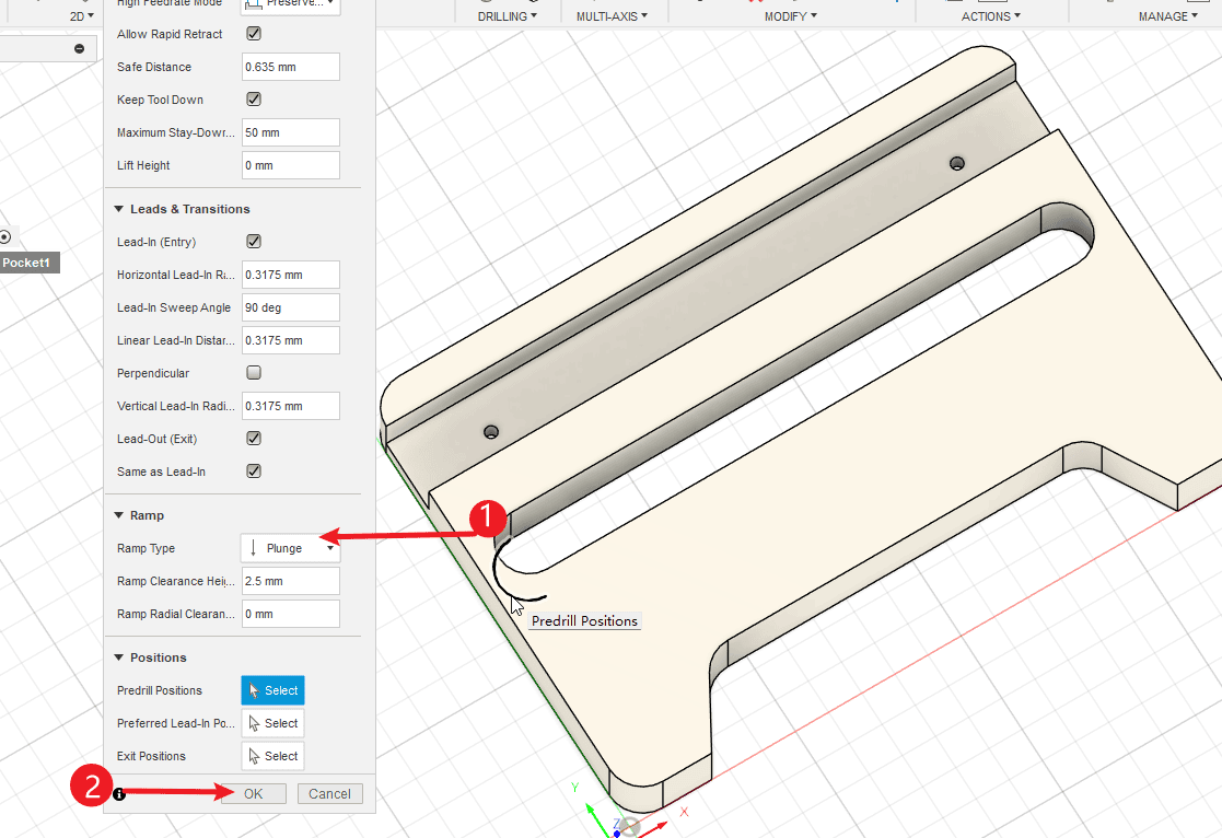
Step 12
Perform the operations according to the sequence numbers.
- 1.Click on the “Connection Settings” section, and change the cutting mode to “Direct Drop”.
- 2.Click “OK” to complete the knife path setting.
|
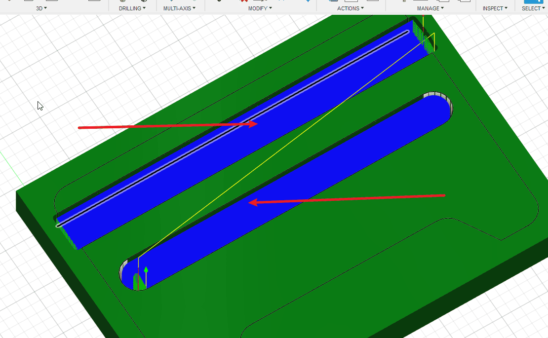
Step 13
- After clicking, you can see the traces of the cutting path.
|
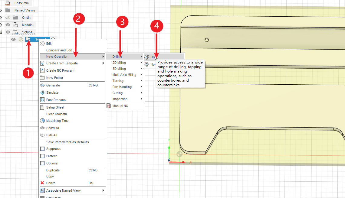
Step 14
Perform the operations according to the sequence numbers.
- 1.Right-click the programming environment and create a new cutting path again.
- 2.Click on the “New” operation
- 3.Click on the drill hole
- 4.Click hole
|
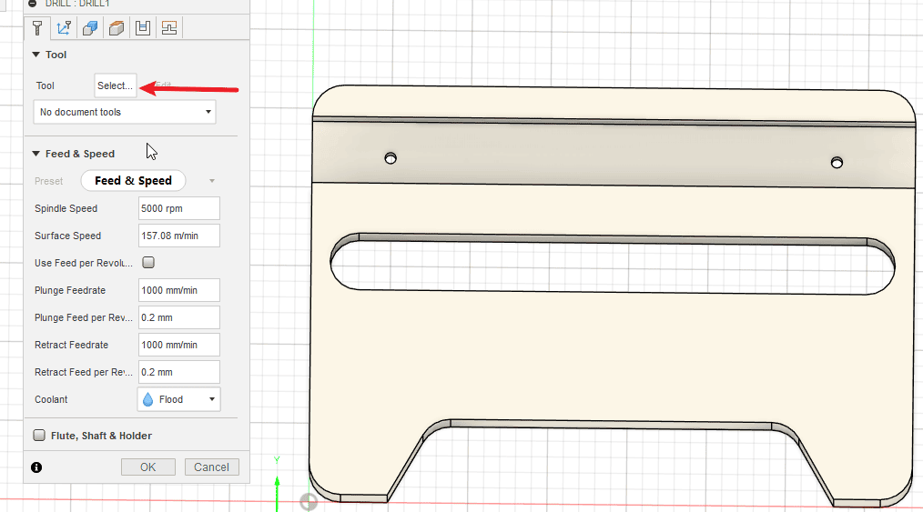
Step 15
- Select the tools that need to be used
|
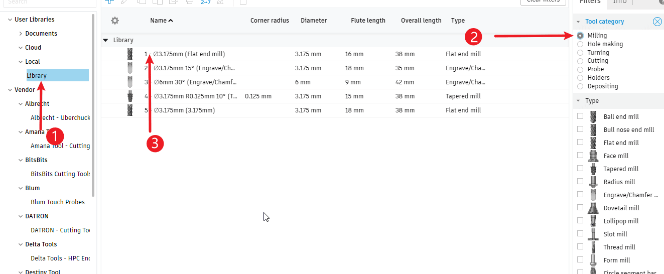
Step 16
Perform the operations according to the sequence numbers.
- 1.Click on the local area
- 2.Click on the milling tool. If a drill bit with a hole is added, you can also directly select the drill bit.
- 3.Click on the tool you need to use and confirm.
|
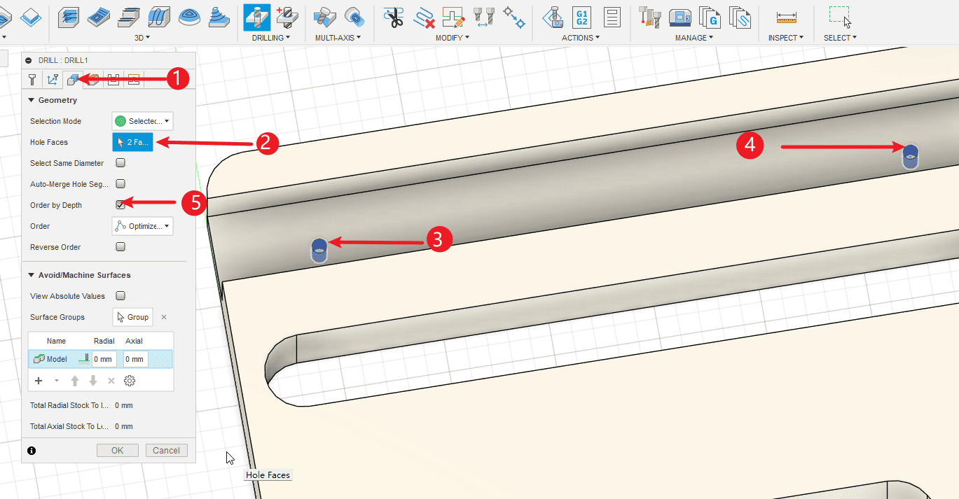
Step 17
Perform the operations according to the sequence numbers.
- 1.Click on the shape
- 2.Click to select
- 3-4.Check all the features of the holes
- 5.Click to sort by depth
|
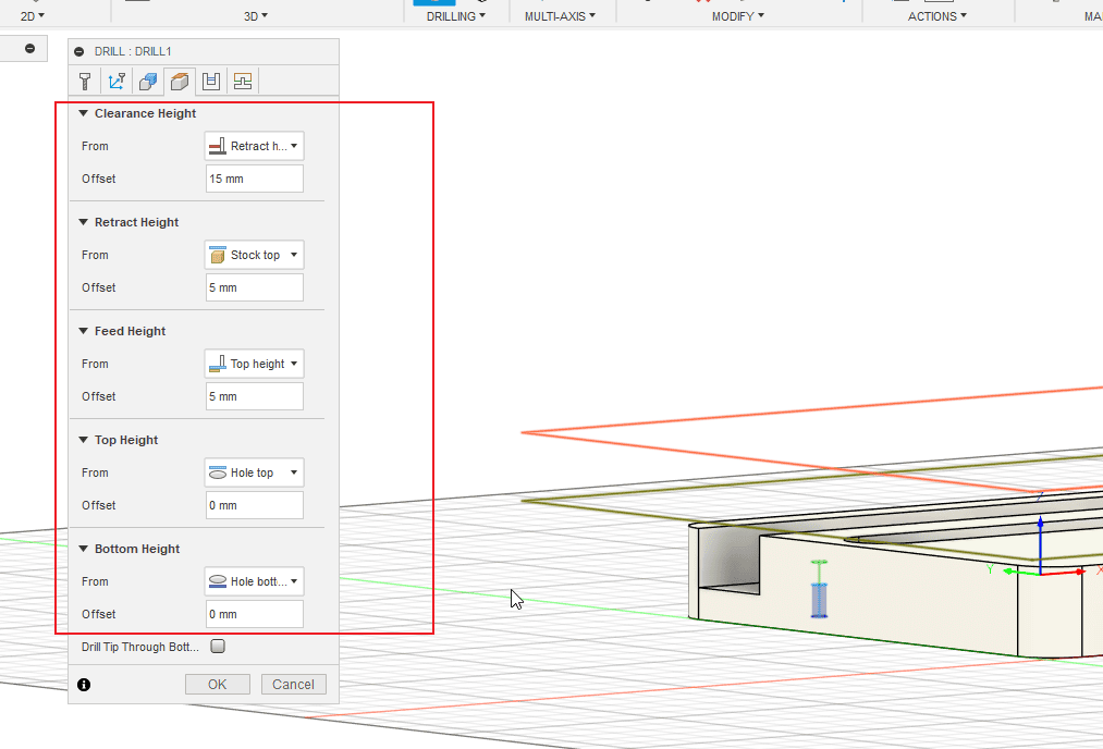
Step 18
- The height setting usually defaults to the standard value. Alternatively, you can increase the safety height by a little in the settings.
|
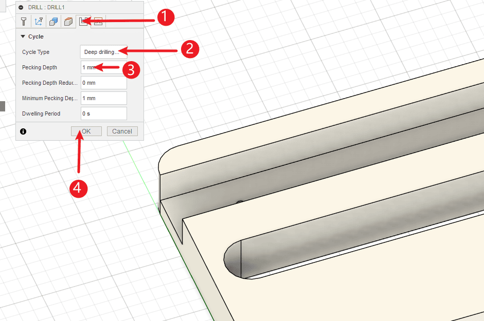
Step 19
Perform the operations according to the sequence numbers.
- 1.Click path
- 2.The drilling mode should be set to deep drilling - complete retraction mode.
- 3.Set the depth of the drill bit
- 4.Click “OK” to complete the drilling instruction.
|
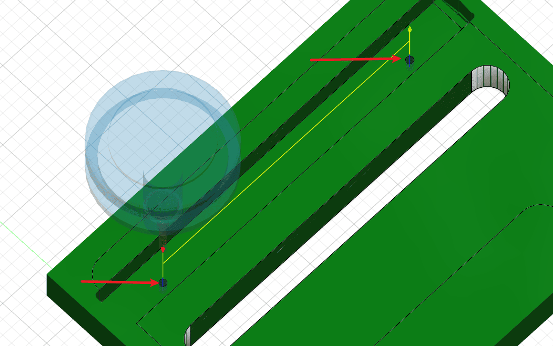
Step 20
- Check the path of the drill hole
|
Step 21
Perform the operations according to the sequence numbers.
- 1.Right-click environment
- 2.Recreate operation again
- 3.Select 2D operation
- 4.Select 2D contour
|
Step 22
- Click “Add Tool” to add the tools you need to use.
|
Step 23
Perform the operations according to the sequence numbers.
- 1.Select by clicking “Select”
- 2.Click on the contour that needs to be cut
|
Step 24
Perform the operations according to the sequence numbers.
- 1.Click on the processing path
- 2.Click on the two-way option
- 3.Select layered milling
- 4.Set the depth of each cut, and click “Finish” to proceed.
|
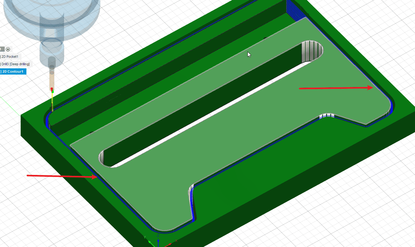
Step 25
- Observe the contour cutting path
|
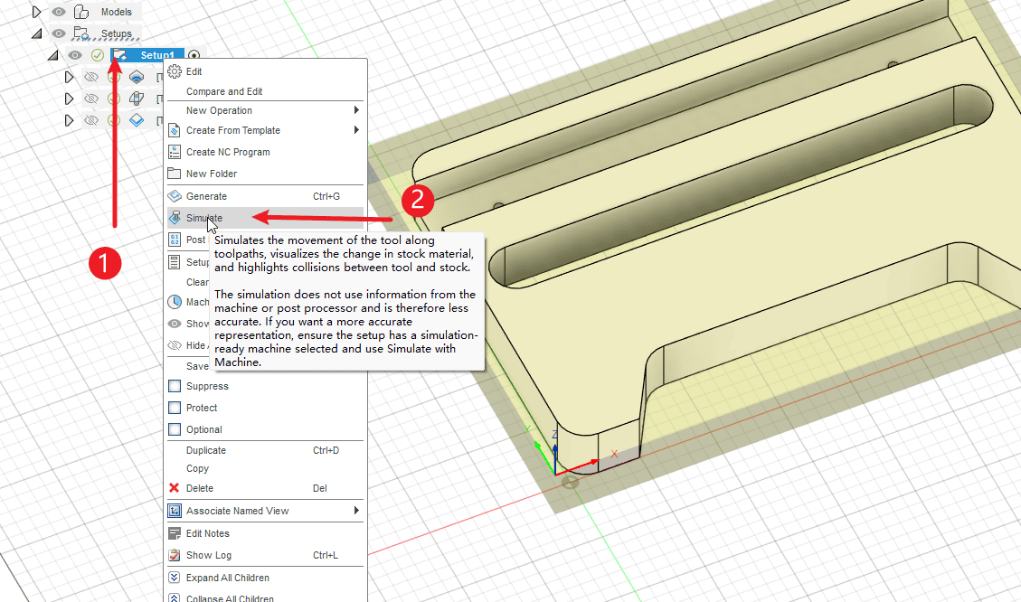
Step 26
Perform the operations according to the sequence numbers.
- 1.Right-click to set the environment
- 2.Click on “Simulation” to simulate the entire process.
|
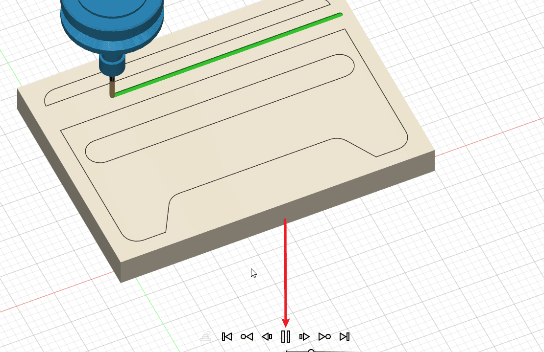
Step 27
- Click to play and you can watch the operation process of the knife path.
|
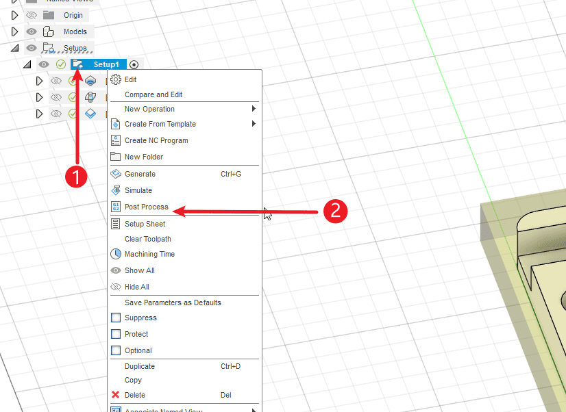
Step 28
- 1.Right-click to set the environment
- 2.Click for post-processing
|
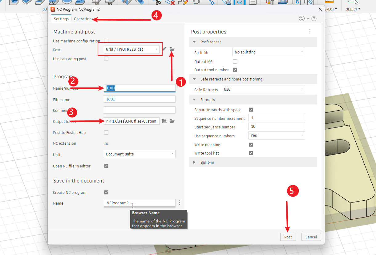
Step 29
Perform the operations according to the sequence numbers.
- 1.Select the imported post-processor
- 2.Name the file
- 3.Set the location for exporting the NC file
- 4.If there are multiple knives in your file, I’m sorry, then you need to split the file. You can click on the operation and select “Make a single NC file from the same knife tool path”.
- 5.Click “Export” and you can find the saved NC file in the corresponding folder.
|