¶ FreeCAD (2D plane programming)
Preface:
This tutorial demonstrates the use of 20mm thick pine boards to make the legs of a computer height-increasing stand, a simple yet very practical small project

|
Core steps:
- Process a 10mm slot using the trenching function.
- The contour cutting command is used to complete the cutting of the workpiece’s shape.
Operation prompt: You can adjust the specific size according to the existing materials. Following the tutorial and getting hands-on practice is the key to mastering skills!
¶ Programming steps
Step 1
First, a new file needs to be created

|
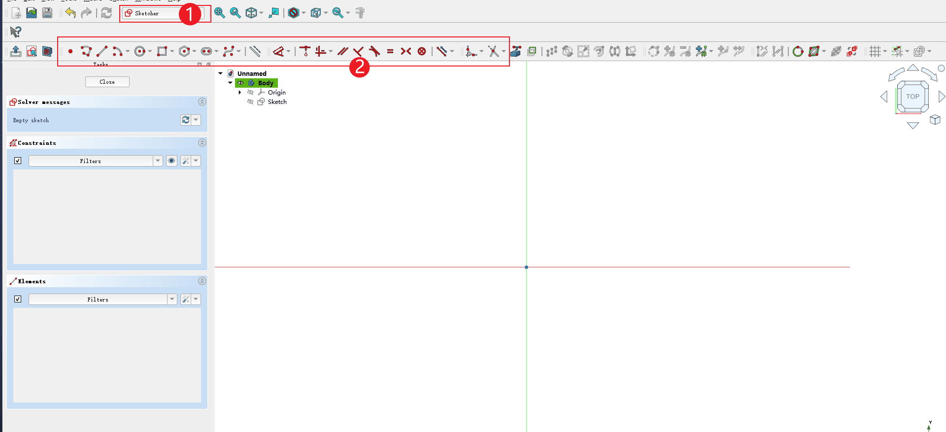
Step 2
Then select the design workbench (just operate in the order of the pictures)
- 1.Select the design workbench
- 2.Create a new sketch

|
Step 3
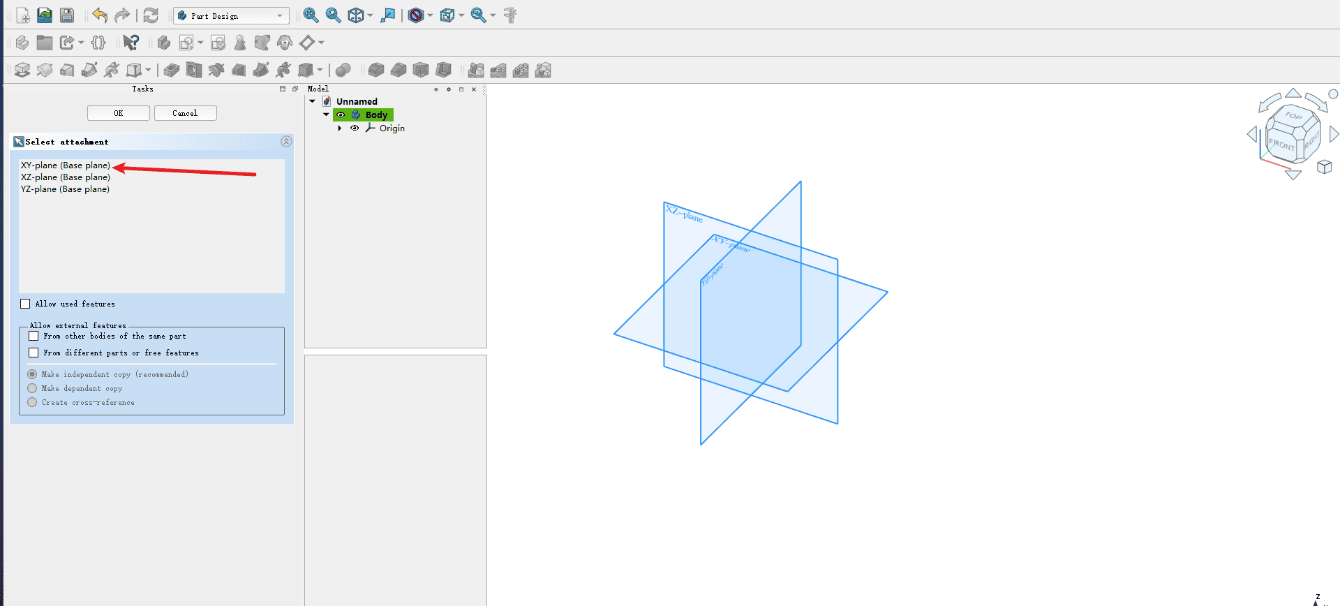
Select a drawing plane (the XY plane is selected in the figure)
|
Step 4
Operate according to the numbers in the picture, draw by referring to the graphics below, and modify the dimensions according to the existing board and the required dimensions
- 1.The workbench will turn into a sketch design
- 2.Use the tools in the toolbar to draw
|
示例图

|
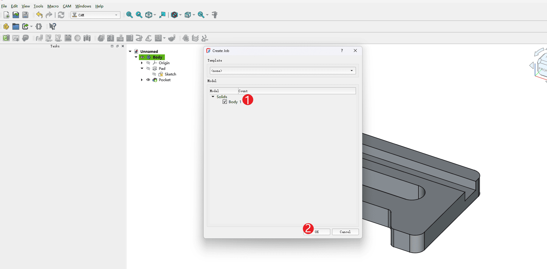
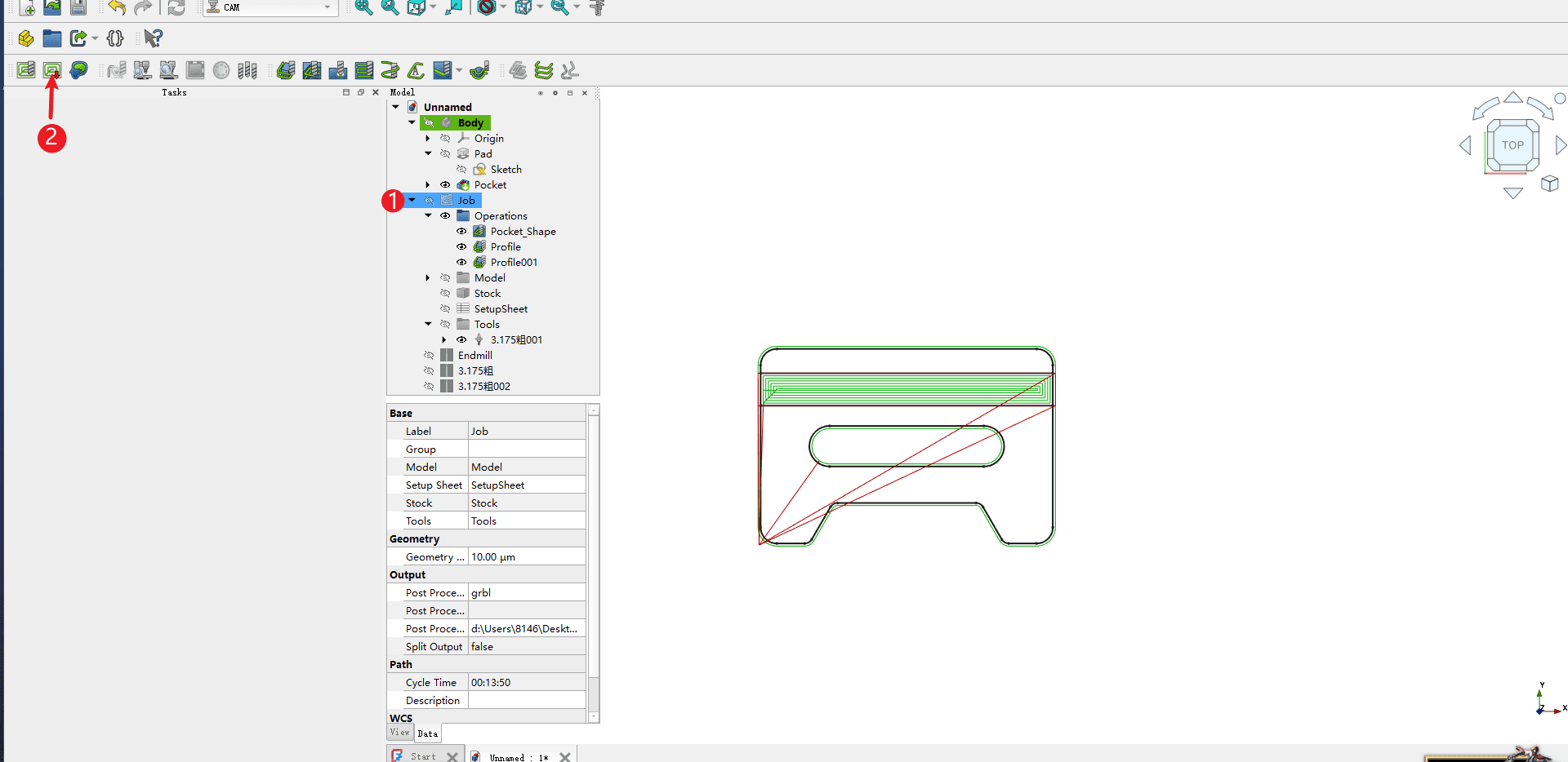
Step 5
After the drawing is completed, please operate according to the numbers in the picture
-
1.Confirm whether the graphic size is correct
-
2.In the workbench options, select CAM to enter the CAM programming environment
-
3.Create a programming assignment

|
Step 6
Operate according to the numbers in the picture
- 1.Check the box of the made model
- 2.Click “OK” to open
|
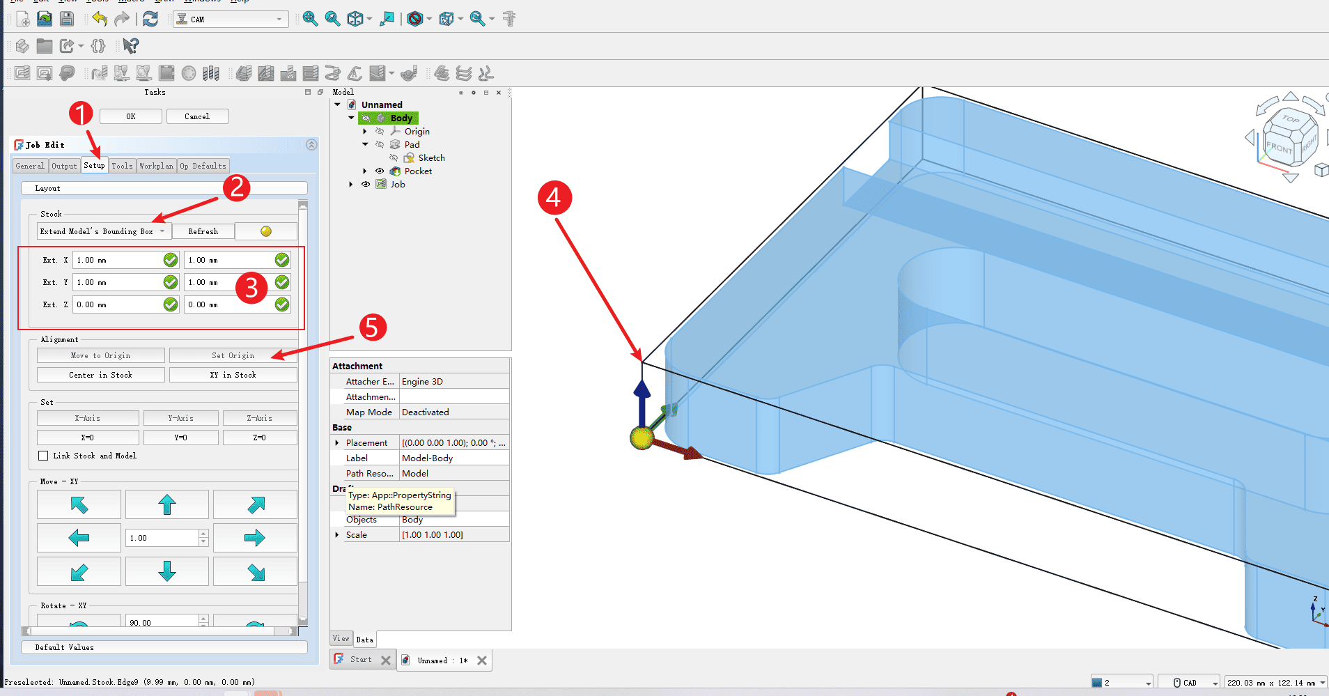
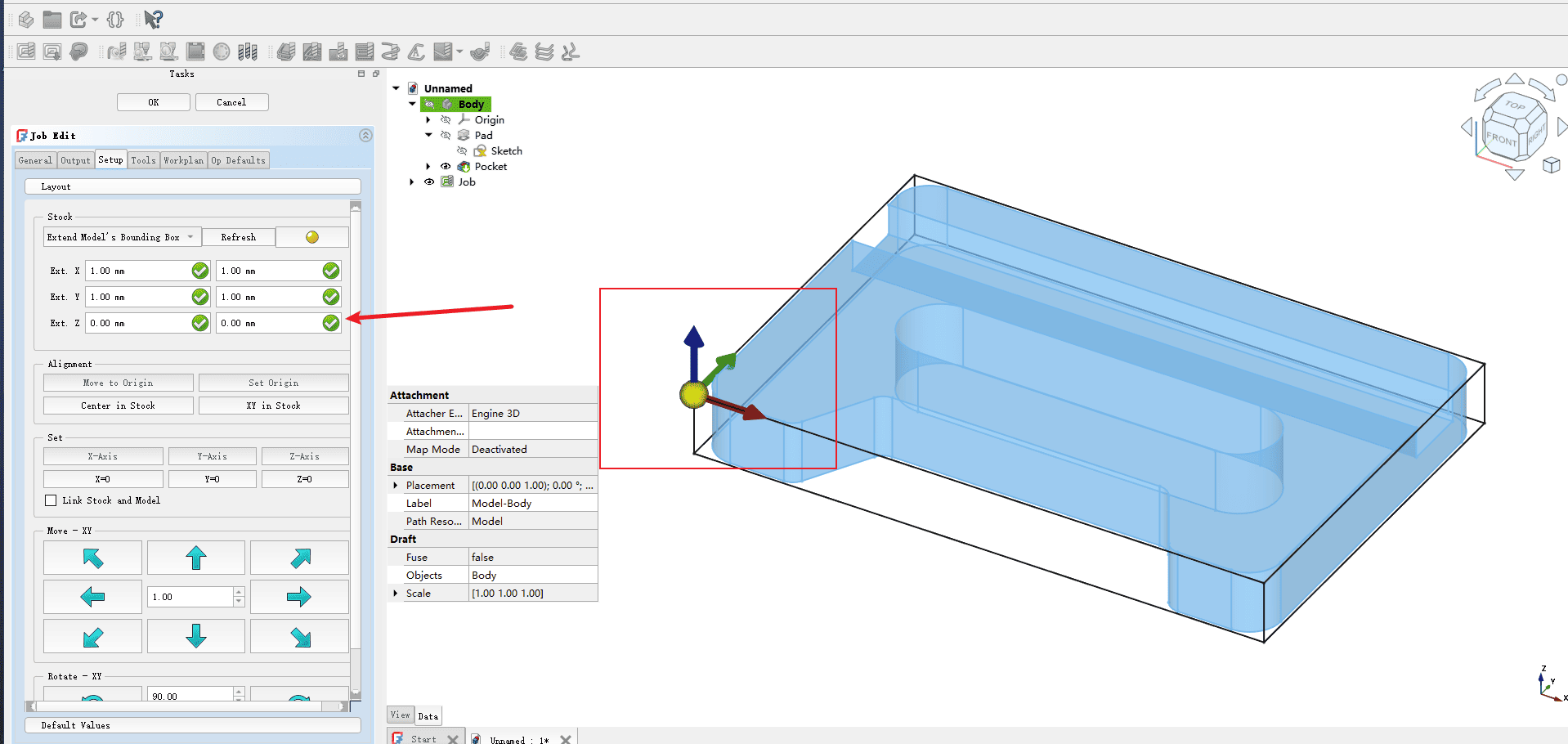
Step 7
Operate according to the numbers in the picture
- 1.Click to set
- 2.Select the edge box of the extended model
- 3.The left and right expansion of XY by 1mm is sufficient (if your sheet is large enough, it can be expanded a little), and the expansion of the Z-axis does not need to be set
- 4.Click on the lower left vertex of the bounding box of the model
- 5.Click “Set Origin” to set the origin on the surface of the material
|
Step 8
After the Settings are completed, please check whether the position of the box arrow within the box is set correctly
|
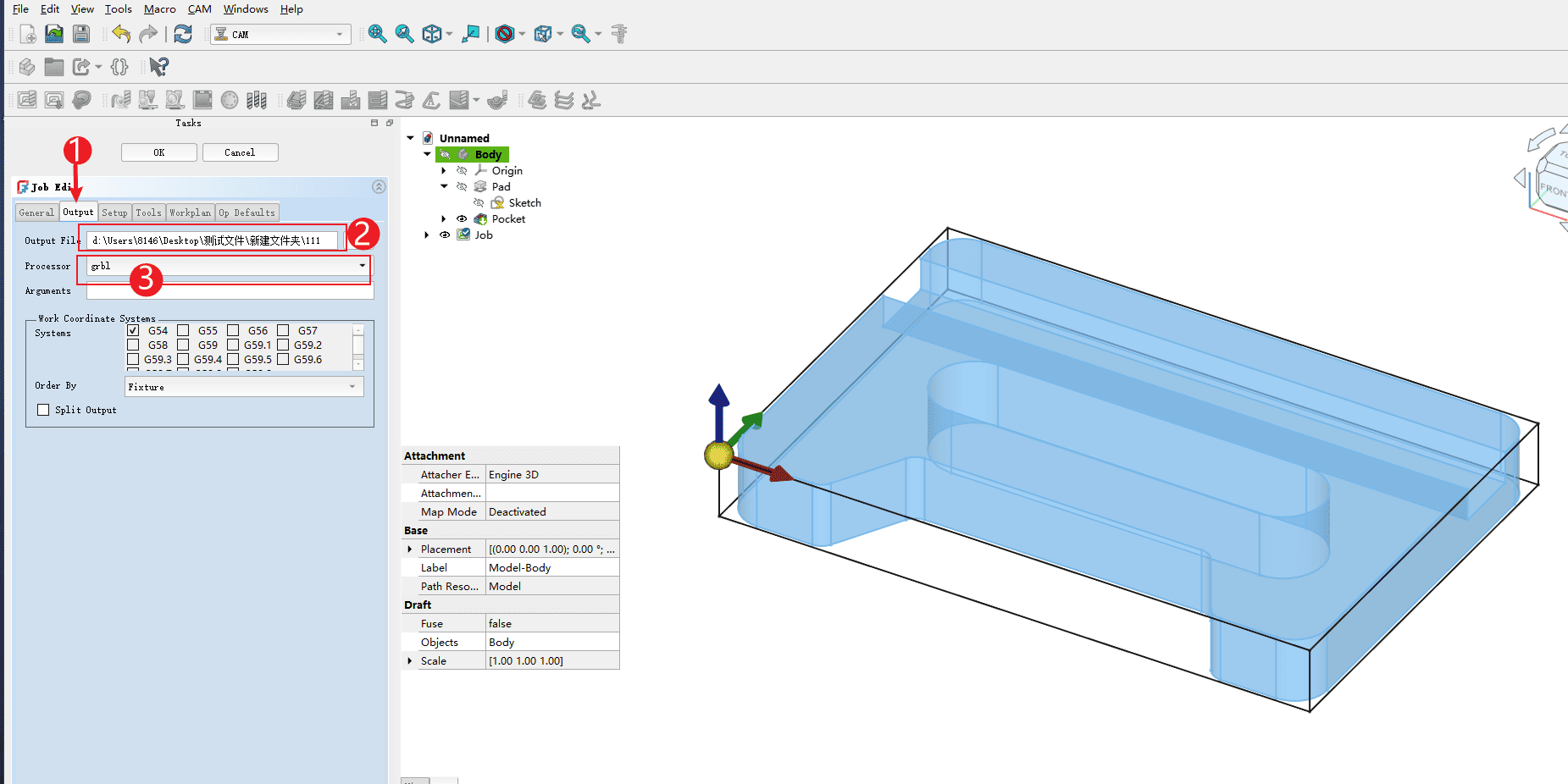
Step 9
Operate according to the numbers in the picture
- 1.Click the output option
- 2.Copy the path where you want to save the file in the output bar
- 3.Select the post-processing as grbl
|
Step 10
Operate according to the numbers in the picture
- 1.Click on the tool option
- 2.Click to add

|
Step 11
Operate according to the numbers in the picture
- 1.Select the redundant knives
- 2.Click to delete
- How to add tools? Please check the tool addition tutorial on the software’s homepage

|
Step 12
Operate according to the numbers in the picture
- 1.Set the cutting rate parameter (
Note: This speed is in mm/s units. It is recommended to convert it based on 80% of the maximum speed of the equipment you own. Do not directly input it according to the diagram) - 2.Set the spindle speed and use 1000 to operate at full power
- 3.Click OK and the programming assignment will be created. Click OK and the programming assignment will be created

|
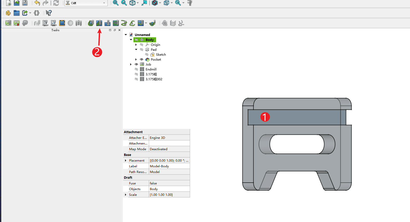
Step 13
Operate according to the numbers in the picture
- 1.Click on the slot to be processed, and the corresponding position will be highlighted
- 2.Click on the slot to be processed, and the corresponding position will be highlighted
|
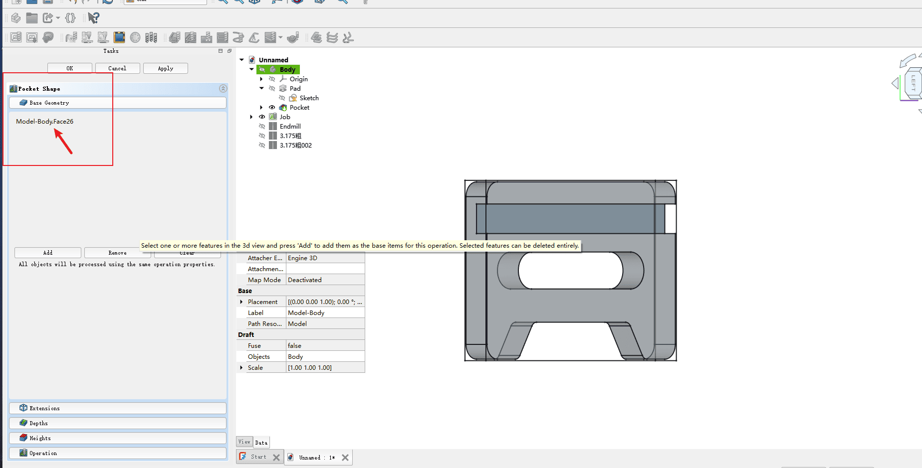
Step 14
Check if the basic graphic selection in the red box is checked. If it is checked, proceed to the next step
|
Step 15
Operate according to the numbers in the picture
Click on the depth indicated by the arrow
- 1.Starting depth: Since the origin is at the lower left corner of the model’s upper surface, it can be set to 0
- 2.Completion depth: It refers to the depth you need to cut. The slot in the picture is 10mm. Since the origin is on the surface, it is set to -10. The same applies to other depths
- 3.Step size: It refers to the depth of cutting off each layer in layer-by-layer milling. Here, 1mm is sufficient. (Note: If the material hardness is high, the depth of cutting off each layer should be appropriately reduced.)
- 4.Completion step size: No setting is required here

|
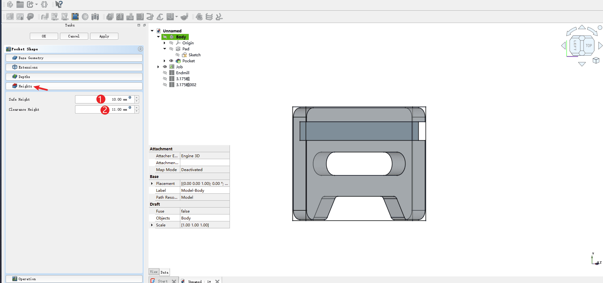
Step 16
Operate according to the numbers in the picture
Click the height according to the arrow
- 1.Safety height: This is the height for lifting the knife, which can be set to 10mm. If your board is thick, you can appropriately reduce this height, but it should not be lower than 5mm to avoid triggering the limit
- 2.Clear height: Here, it can be set a little more than the safety level. In the picture, it is set to 11mm
|
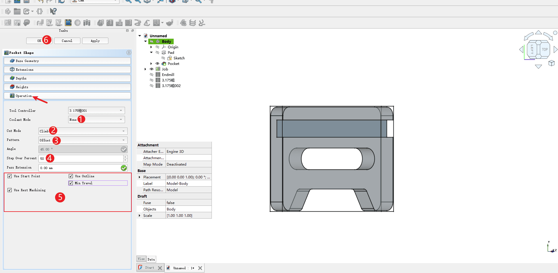
Step 17
Operate according to the numbers in the picture
Click to process according to the arrow
- 1.Turn off the coolant (Machines without coolant need to be turned off).
- 2.The cutting mode uses climb milling (it is recommended to use climb milling as it is highly efficient and has low noise)
- 3.The mode uses offset (here referring to the running trajectory of the tool path, with multiple options available).
- 4.The step percentage is 50% (here it refers to the row spacing of each cut, generally using the radius of the tool diameter).
- 5.All the options in the box can be checked
- 6.Click “OK” and the milling path will be completed
|
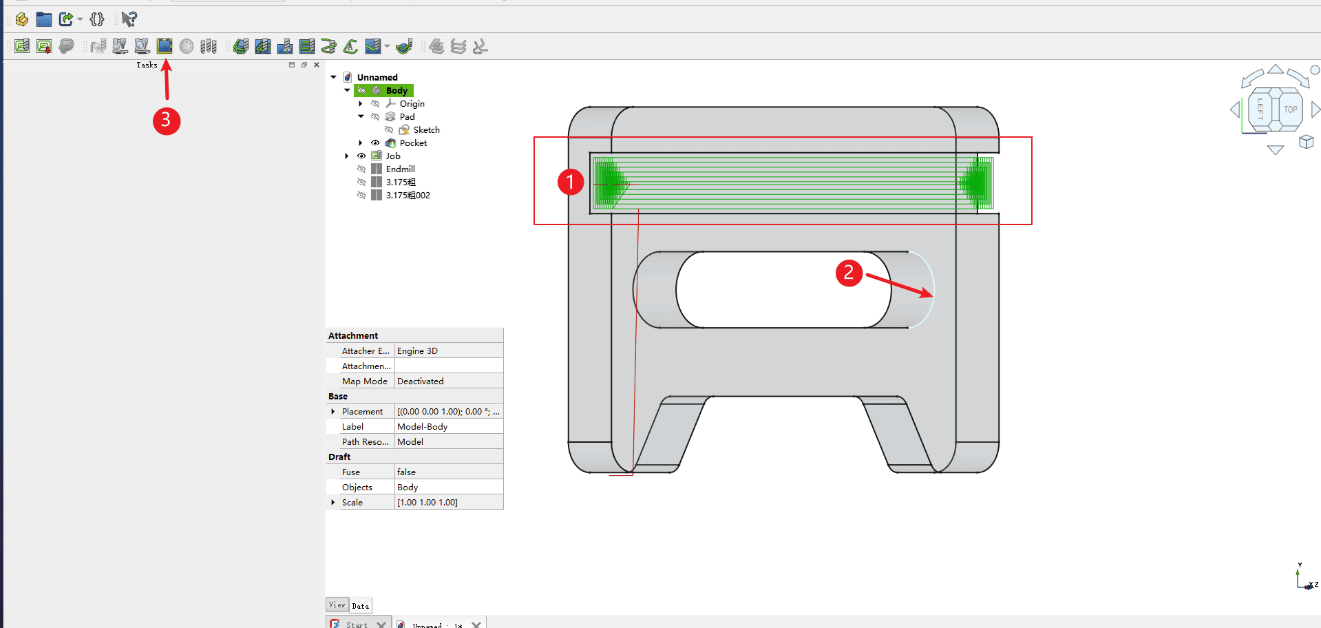
Step 18
Operate according to the numbers in the picture
- 1.Check whether the previous tool path is displayed normally
- 2.Click on the edge line that forms the keyway on the upper surface of the model (’ Note: Be sure to click on the edge line ').
- 3.Click the arrow to complete the selected loop
|
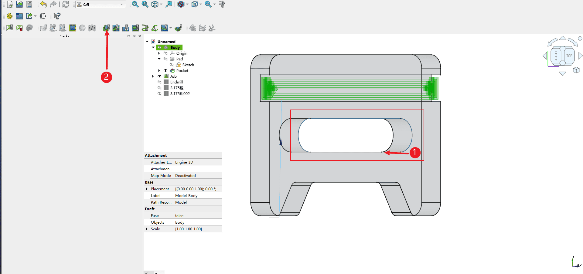
Step 19
Operate according to the numbers in the picture
- 1.Check whether all the edges that make up the keyway in the red box are highlighted (if they are highlighted, it means the box selection is complete and you can proceed to the next step).
- 2.Click the contour command indicated by the arrow to enter the contour tool path programming
|
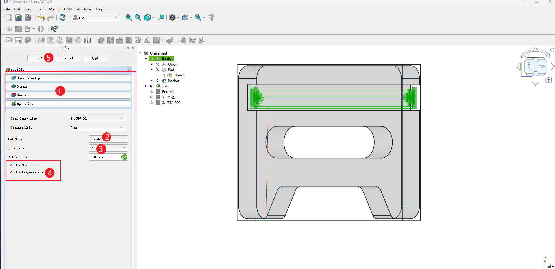
Step 20
Operate according to the numbers in the picture
- 1.The options in the red box can simply follow the parameters of the previous trenching command (
Note: The completion depth in the depth setting needs to be set to the thickness of the wood board used in order to complete the cutting). - 2.Select the inner side for the cutting (
Note: All feature cuts within the part should be made along the inner side for accurate dimensions) - 3.Direction selection: CW
- 4.Check all the items in the red box
- 5.Click OK and the setting of the second contour command is completed
|
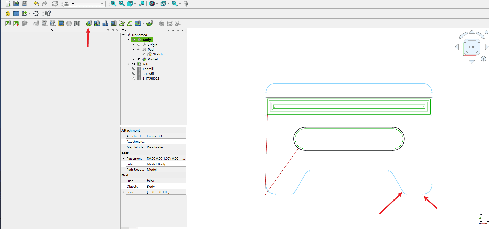
Step 21
The final process is the same as the operation of the previous process. Here, the outer contour lines of the model need to be manually selected one by one until all the lines and points of the entire outer contour are highlighted(Note: The points that form the outer contour line segments should also be selected)
|
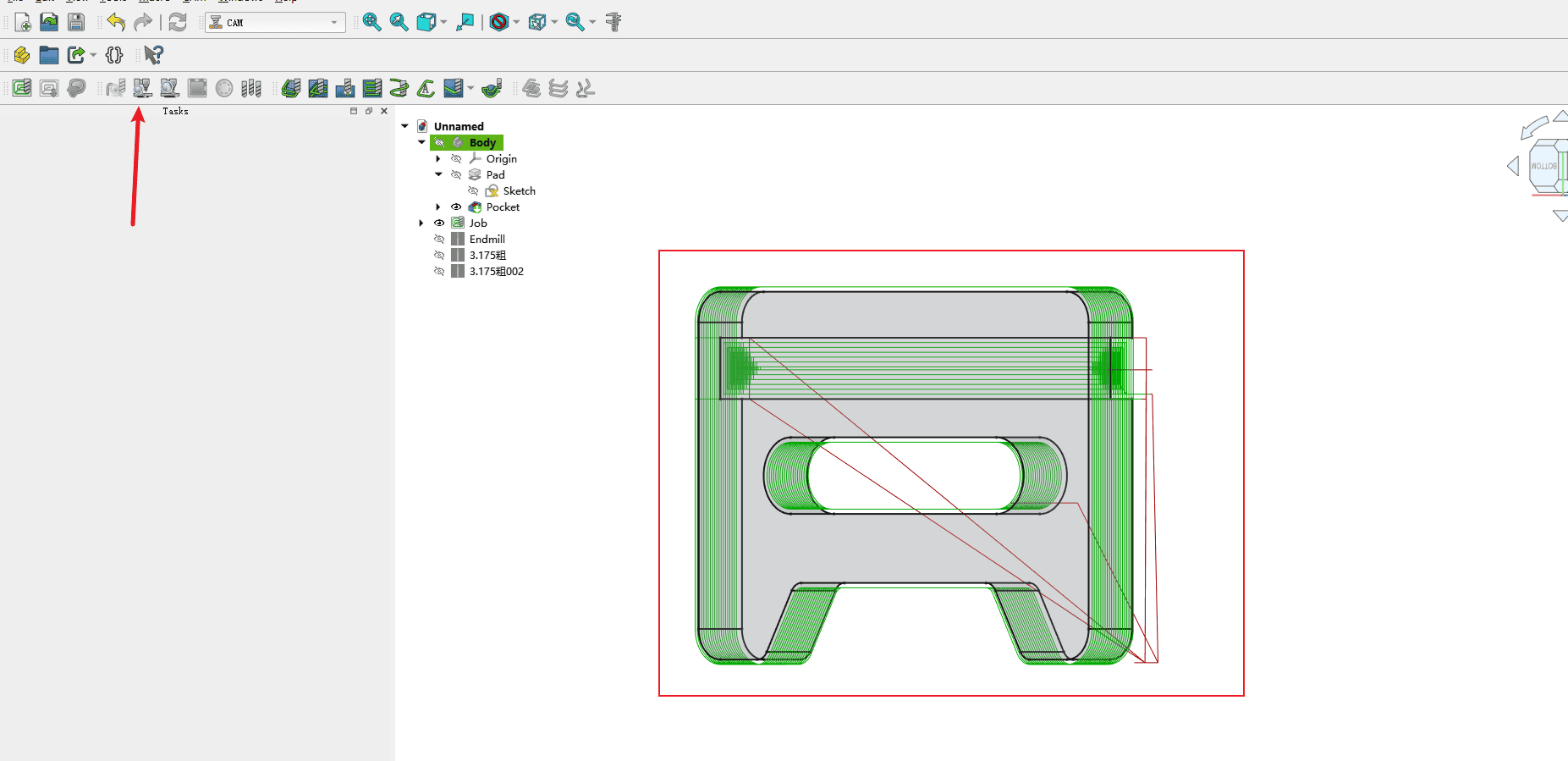
Step 22
After the production is completed, the blade path simulation can be carried out using the simulation command indicated by the arrow
|
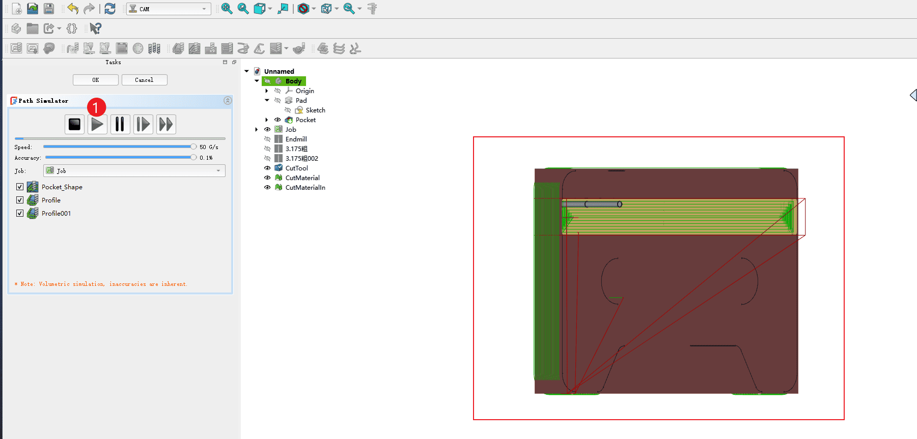
Step 23
Operate according to the numbers in the picture
- 1.Click “Start” to start the dynamic simulation of the tool path. On the right side, you can see the milling process
|
Step 24
Operate according to the serial numbers in the picture
- 1.Click on the created work assignment
- 2.Click “Start Post-processing”, and the file will be automatically post-processed and saved in the folder where you previously filled in the output post-processing
|