¶ Planar engraving
Step 1
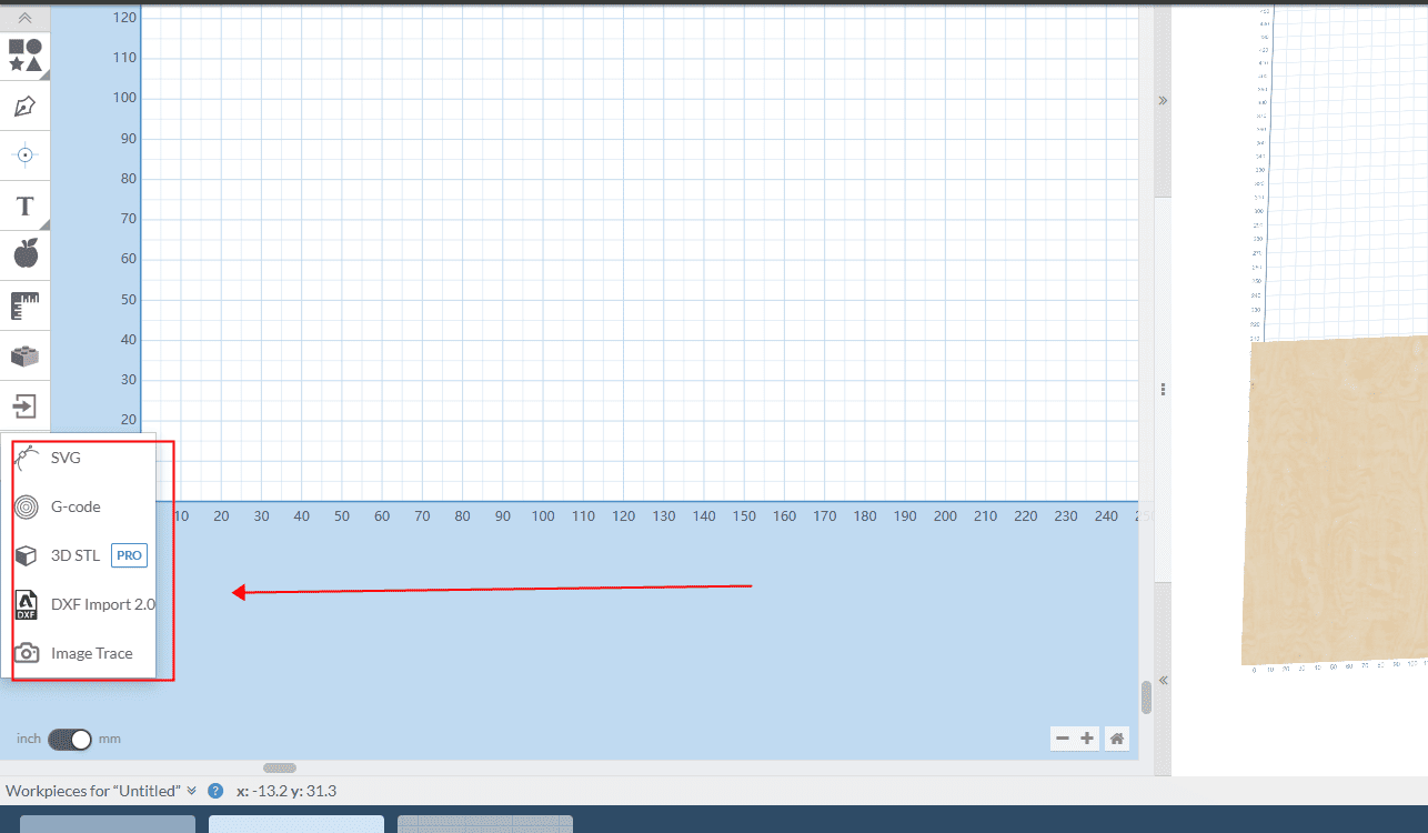
In the right toolbar, select “Import” and choose the format you want to import. The demonstration uses a file in DXF format
|
Step 2
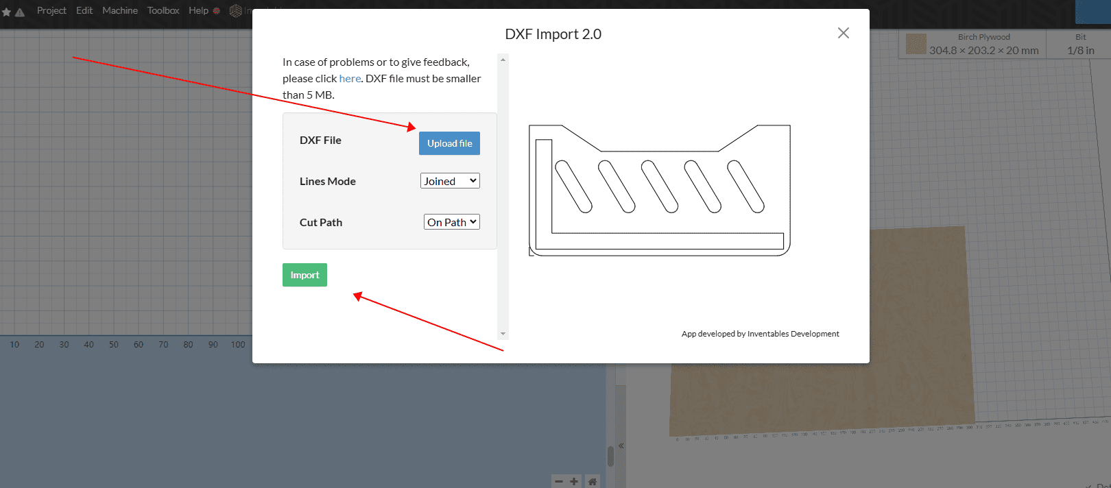
Click “Upload File”, wait for the loading to complete and then confirm
|
Step 3
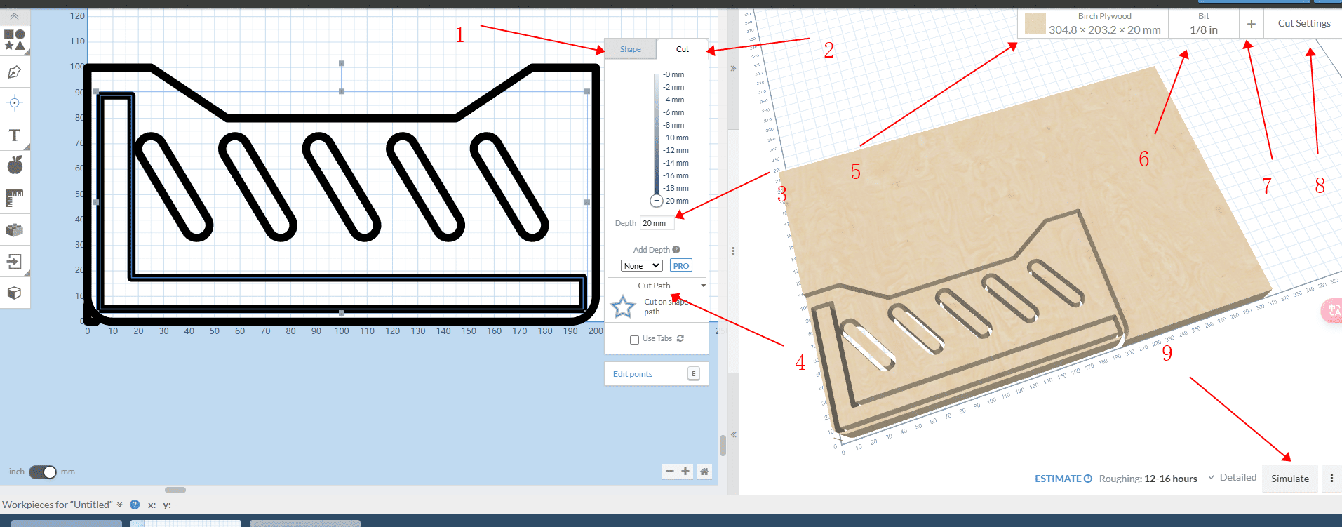
Operate in sequence according to the arrow numbers
- Right-click after selecting a line segment to edit the processing style
- The knife path can be set
- The required processing depth can be set. If penetration is needed, it can be set to the thickness of the material
- You can choose to hollow out or cut this contour. There is a knife path running along the section, running along the inner side or along the outer side. You can set it according to your needs
- This setting is for the material, thickness, length and width of the board. You can set them according to your needs
- Here is the selection of rough machining tools. If it is 2D milling, only one rough machining tool is needed
- Here is the selection of tools for fine processing. If it is 3D relief, a processing tool is required
- This setting is for the tool path. Set the feed rate for machining, the feed rate for down-cutting, the depth of each machining process, and the travel mode of the tool path
- Here is the operation of the simulated tool path. After setting it up, the simulation of the tool path can be carried out
|
Step 4
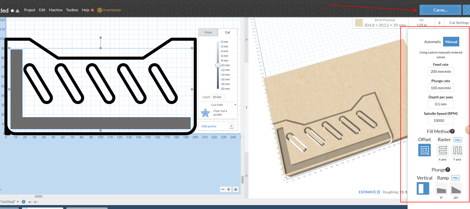
After setting the tool path in the red box and connecting the machine, click “Send File” in the upper right corner to start engraving (you can also choose to download G-code in the project in the upper left corner and use the SD card for engraving).
The feed rate and cutting speed need to be converted based on the speed of the existing model. Do not input directly according to the diagram
|