¶ How to improve your printing skills
Improving the quality of 3D printing can be achieved by:
- Choose the right printing material: Different printing materials have different characteristics, and choosing the material that suits your needs can improve the print quality. For example, ABS, PLA, PETG and other materials have their own advantages and disadvantages, which need to be selected according to the specific situation.
- Adjust the printing temperature: Controlling the printing temperature can affect the fluidity and adhesion of the printing material, thus affecting the print quality. According to the requirements of printing materials, better printing results can be obtained by adjusting the printing temperature.
- Optimize printing parameters Adjusting printing speed, layer height, filling density and other parameters can affect the print quality. In general, slower print speeds and smaller layers allow for higher print quality.
- Calibrate the printer, regularly calibrate the 3D printer, including platform flatness, extruder adjustment, axial adjustment, etc., to ensure printing accuracy and quality.
- Use of support structures and fillers: For complex models, the use of appropriate support structures can improve print quality. In addition, increasing the density of the filler can improve the strength and stability of the print.
- Optimize the model design: when designing the model, consider the feasibility of printing and optimize the structure, reduce excessive hanging, sharp angles and fine details, etc., in order to improve the printing success rate and quality.
- Post-processing: After the printing is completed, appropriate post-processing work, such as grinding, painting, spraying, etc., can improve the surface quality and appearance of the printed product.
- Through the comprehensive use of the above methods, the quality and effect of 3D printing can be significantly improved.
¶ Variable height
1, when a small part of the position of the printing requirements need to be fine, you can achieve this requirement through the variable height of this function: see the details below
This is shown as a cone file, and the software uses orca-slicer for demonstration (the same applies to other software).
Select variable height (Figure 1)
(Figure 1)
- The red arrow refers to the smooth distance between the changed part and the unchanged part, the white arrow represents the normal height of 0.2, and the green on the model and the progress bar on the right is the position where the height needs to be changed
- (Figure 2) By clicking the left mouse button in the progress bar, the height of the selected part can be reduced, and the right mouse button can increase the height of the selected part (between 0.08-0.28), which can be changed according to demand
(Figure 2)
(Figure 3) The layer height of the green part in the figure is 0.08, the layer height of the red part is 0.28, and the distance between red and green is smooth, so the variable layer height adjustment is completed
(Figure 3)
¶ Print piece by piece
1, piece-by-piece printing is a technology used to deal with one-time printing at the same time, but also to avoid multiple parts to switch back several times caused by drawing between parts
2, the order of printing one by one should be from simple structure to complex, from low to high order, printing in turn, please see below for details:
orca-slicer is used as a demonstration (as with any other software).
Open the software and click other according to the operation in (Figure 1), find the printing order in the special mode, and switch the layer by layer printing to piece by piece printing
(Figure 1)
Then add the parts, the placement of the parts should be the same as the edge line pointed by the arrow in (Figure 2), can not coincide!!!
(Figure 2)
Finally, click the section according to the blue arrow in (Figure 3), and the setting of printing piece by piece is completed
¶ How to fix the mode
In 3D printing, there will be some mistakes in the drawing of models resulting in broken surfaces or loss of details, which can be repaired simply through software
When the model is wrong, the software will prompt in the red box at the lower right corner (Figure 1), and we can click the repair option indicated by the green arrow next to it to repair it.
¶ How to simplify the model
Some fine models have too many triangular surfaces, which will lead to excessive load of slicing software resulting in stalling and slicing failure, which can be solved by simplifying the model
1.Right-click the model and select the simplified model in Figure 1, and then check the option pointed by the blue arrow in Figure 2 to see the triangular surface intuitively.
Then you can choose high quality or low quality by the change of the triangular surface of the following two graphs
¶ 3D text
In software we can add text to the model, which increases the uniqueness of a model
1.Right-click the model to open (Figure 1) add modifier and select text emboss
2.In the green box (Figure 1.2), you can move the direction, and adjust the text and thickness in the blue box
¶ Machine calibration tutorial
¶ Flow calibration
When the top surface of your part has excessive extrusion or flow loss, a flow calibration is required to correct the problem
(Figure 1) is excess extrusion (Figure 1.1) is correct extrusion (Figure 1.2) is flow missing
Press (Figure 2) to open the slicing software (orca-slicer is used for demonstration here, and other software is the same). Click the calibration bar in the green box, find the flow bar and select Pass 1. 9 plane models will be generated on the table surface, click the slice and print them out
(Figure 2)
(Figure 3) The square will have the corresponding value, the number of square 0 represents 100% extrusion, attention!! (The flow ratio here is calculated as a percentage), after the printing is completed, according to the observation (Figure 3.1), which top surface is the smoothest. Here I choose box No. 5, and you can scrape the surface with your finger. The smaller the resistance, the smoother the surface
(Figure 3)
Then open the consumables parameters according to (Figure 4) and find the flow ratio in (Figure 4.1), the formula here is: the old value * (100 ± the square you selected)/100, I chose the box No. 5:0.98x(100+5)/100 = 1.029
Re-enter the calculated flow ratio, then delete the original 9 squares, and click the calibration interface again to select Pass 2 according to (Figure 5) for the second fine-tuning. The interface will prompt you (Figure 5.1) to select migration and re-add
After printing it out, select a square with the best top surface to recalculate it. The square with the -4 number I selected in (Figure 6) is 1.029* (100-4) /100=0.98784, and re-input it into the software to complete all steps
¶ Pressure advance
In 3D printing, there is a delay between the time the extruder applies pressure to the consumables and the time the consumables are extruded, which can lead to uneven extrusion of the consumables around the corner, and using pressure advance can ensure that the nozzle extrudes the same amount of consumables at each print position.
1.First, we open the slicing software, here orca-slicer is used for demonstration (the same applies to other software), open the calibration interface according to (Figure 1), and select the pressure advance
2.orca-slicer provides three measurement methods: linear, tower, V-shaped, each of which has a short range extruder and a long range extruder.
3.We used a short-range extruder with a V-shaped scheme to test. After entering the value in the box (Figure 1.1), click OK to directly slice and print
After printing is complete, find the sharpest and fullest line at the right Angle in (Figure 2), and then open the consumables Settings according to (Figure 2.1), open the pressure in advance, and input the found value (I am 0.056 here) into the save.
¶ Temperature tower test
The temperature tower is a simple temporary tower model, consisting of several blocks each printed at a different temperature to determine the optimal printing temperature for different consumables.
1.Open the calibration interface (Figure 1) and select the temperature
2.In the dialog box that pops up in (Figure 1.2), select the consumables to be tested, start temperature and end temperature, and click OK to print them out
Then choose the right temperature
¶ Pullback calibration
This standard is used to test the drawing caused by the switch between different parts or multiple parts when the consumables are printed. When calibrating the value, the temperature test should be done first to ensure the accuracy of the withdrawal value.
- Open the calibration page in the software, select the callback test, (Figure 1) the pop-up dialog box will be input according to the content selected in the box and click OK, two columns will be generated for easy observation
- After the printing is completed, we can carefully observe the printing results to determine the best withdrawback distance. The optimal draw distance is usually the draw distance corresponding to the layer that produces the least drawn wire. If there are multiple layers of drawing as clean, choose the shortest one back.
Note: When testing with non-wire-drawing consumables such as PLA or ABS, you may find that any degree of pull-back is effective, and the entire pull-back tower is not brushed from beginning to end. If this happens, set the pullback length to any value between 0.2mm and 0.4mm in the consumables Settings.
¶ Maximum volume flow
This test can be used to calibrate the maximum volume velocity of a given consumable. The maximum volume flow preset in the consumables wire configuration built into Orca Slicer may not be accurate enough. Use this test to calculate the maximum volume flow you can achieve with the consumables you actually use.
1.Open the software according to (Figure 1) to find calibration, select advanced calibration and select maximum volume calibration
2. In the pop-up dialog box, fill in the value as shown in Figure 1.1, click OK and print it out
After the printing is completed, find the first layer of print defects from the bottom up, especially pay attention to the change of the wall from froth to smooth texture, use a caliper or ruler to measure the height of the first layer of print defects to the bottom, and calculate the maximum volume flow of consumables with the following formula: initial flow +(the height of the first print defect * step)
As measured in (Figure 2) is 33.2, the corresponding maximum volume flow rate is 5 + (33.2 * 0.5)=21.6, that is, 21mm³/s (an integer is good). Fill this value into the maximum volume velocity column in the consumables setting (Figure 2.1).
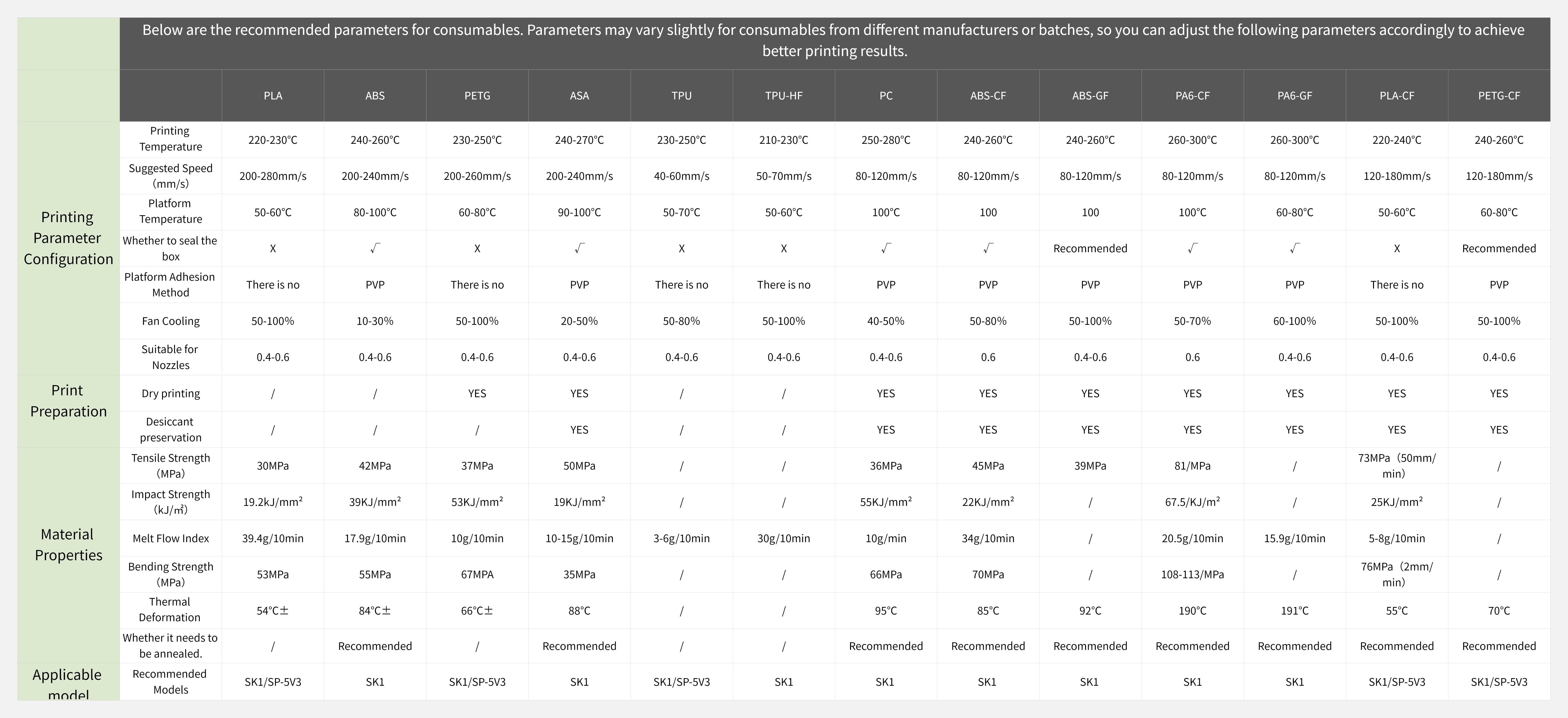
¶ Print parameter recommendation
|