¶ 450Pro Installation Tutorial for F65A Spindle
This tutorial mainly explains how to install the F65A spindle on the TTC450Pro(25) model. You can either follow the tutorial for installation or watch the tutorial video provided below.
¶ Hardware installation
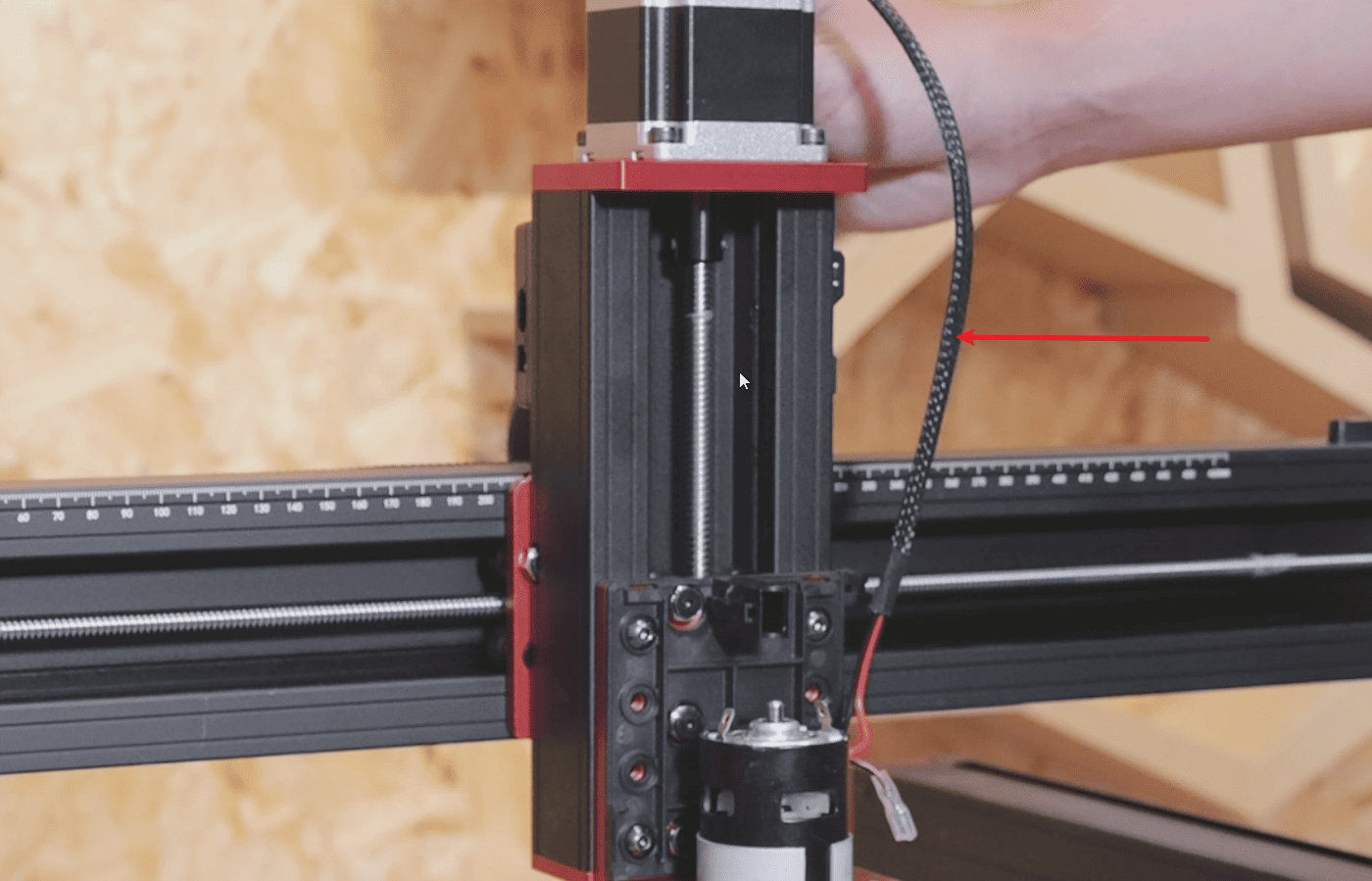
1.Remove the protective cover of the spindle and unplug the power cord of the spindle.
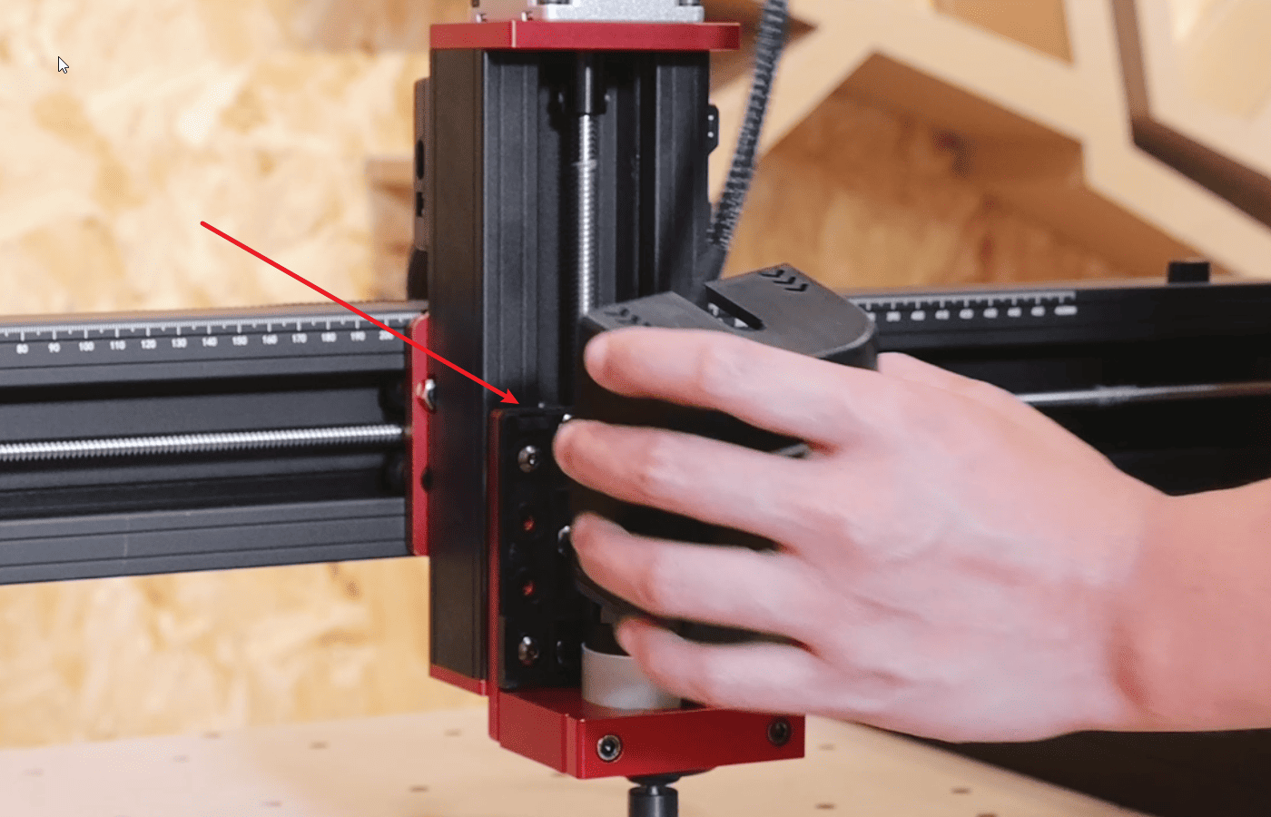
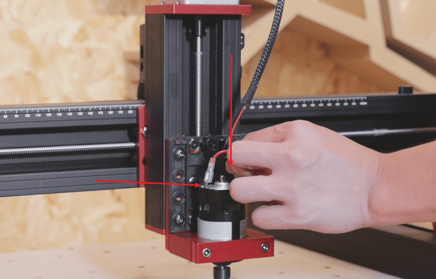
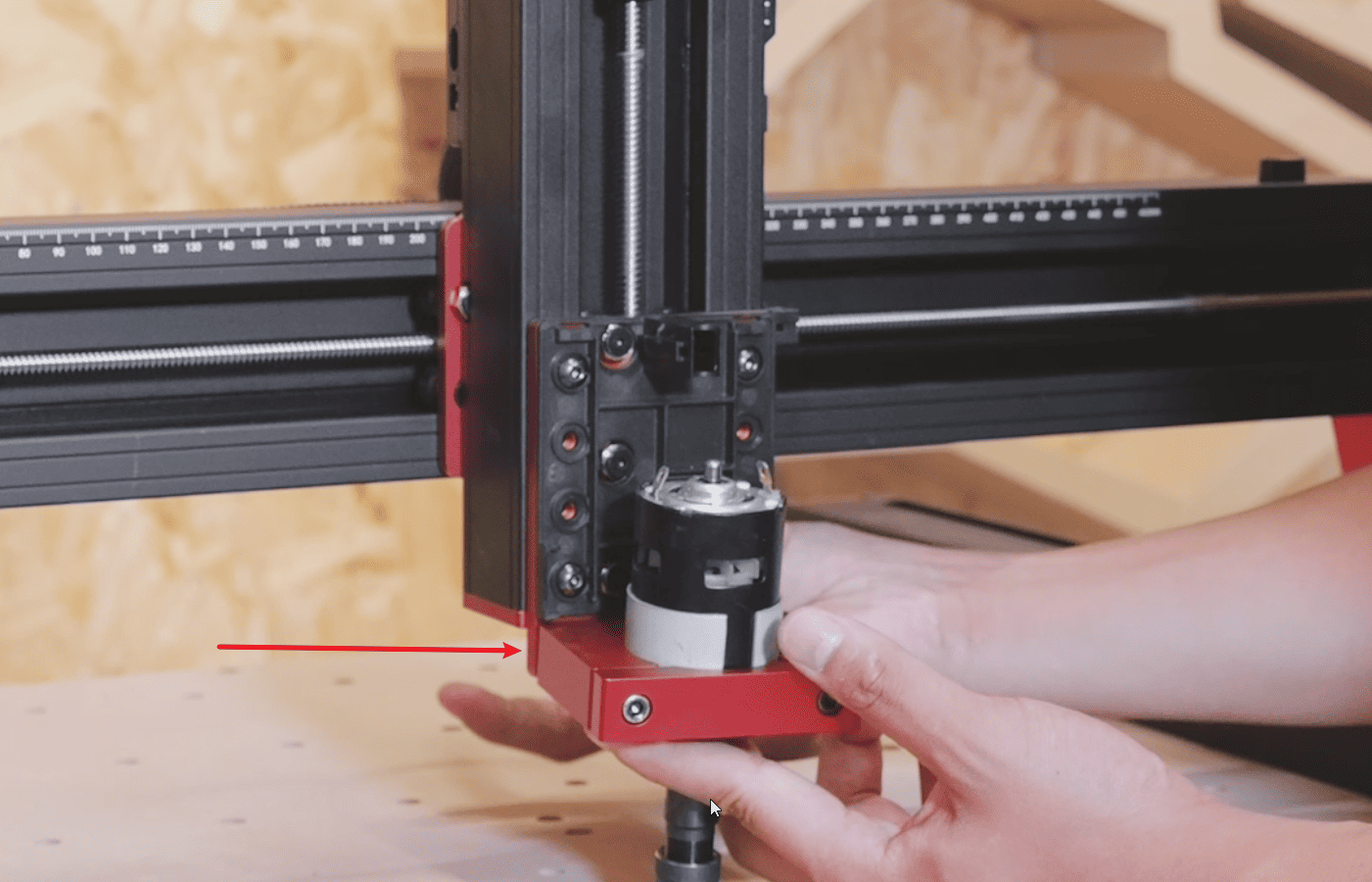
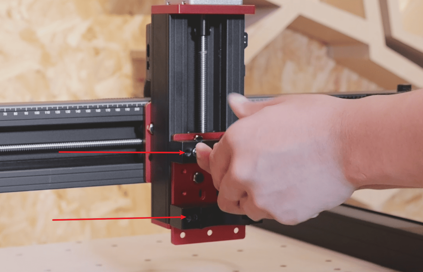
2.Remove the power supply line of the main shaft from the Z-axis adapter board, then loosen the fixing screws of the original main shaft fixture and remove the entire 775 main shaft.
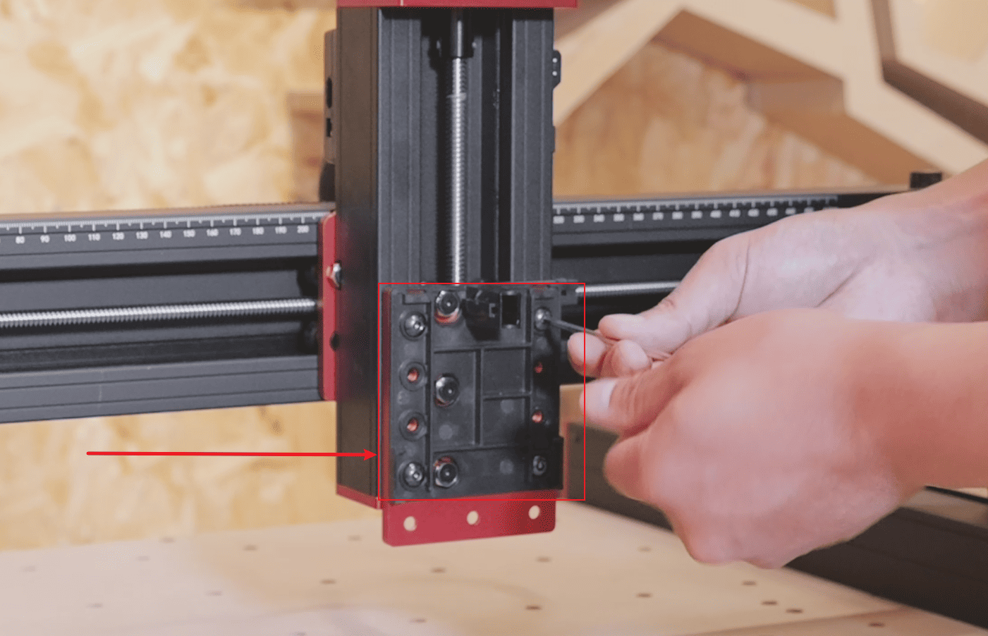
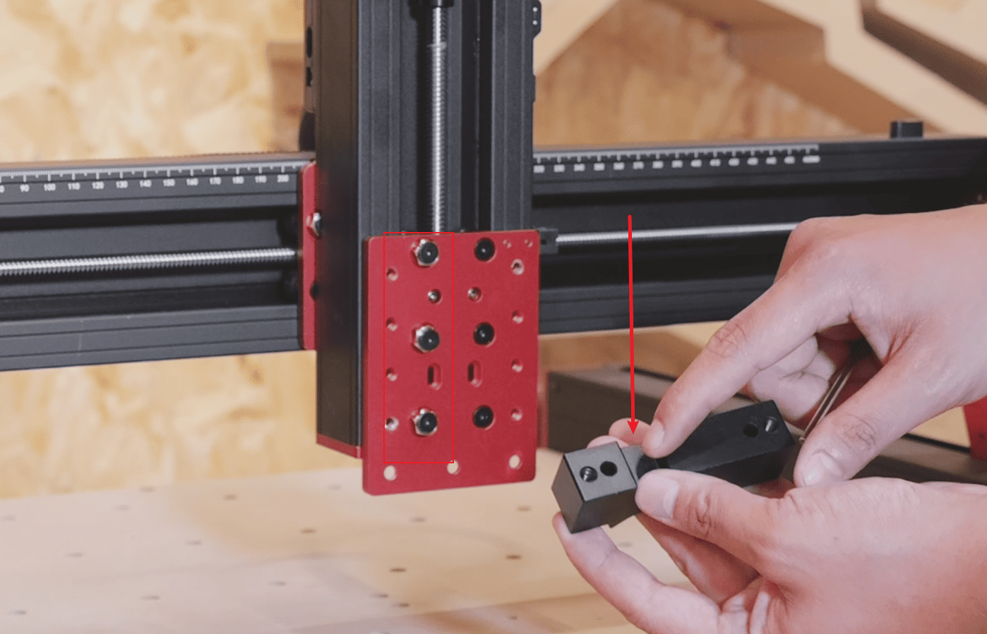
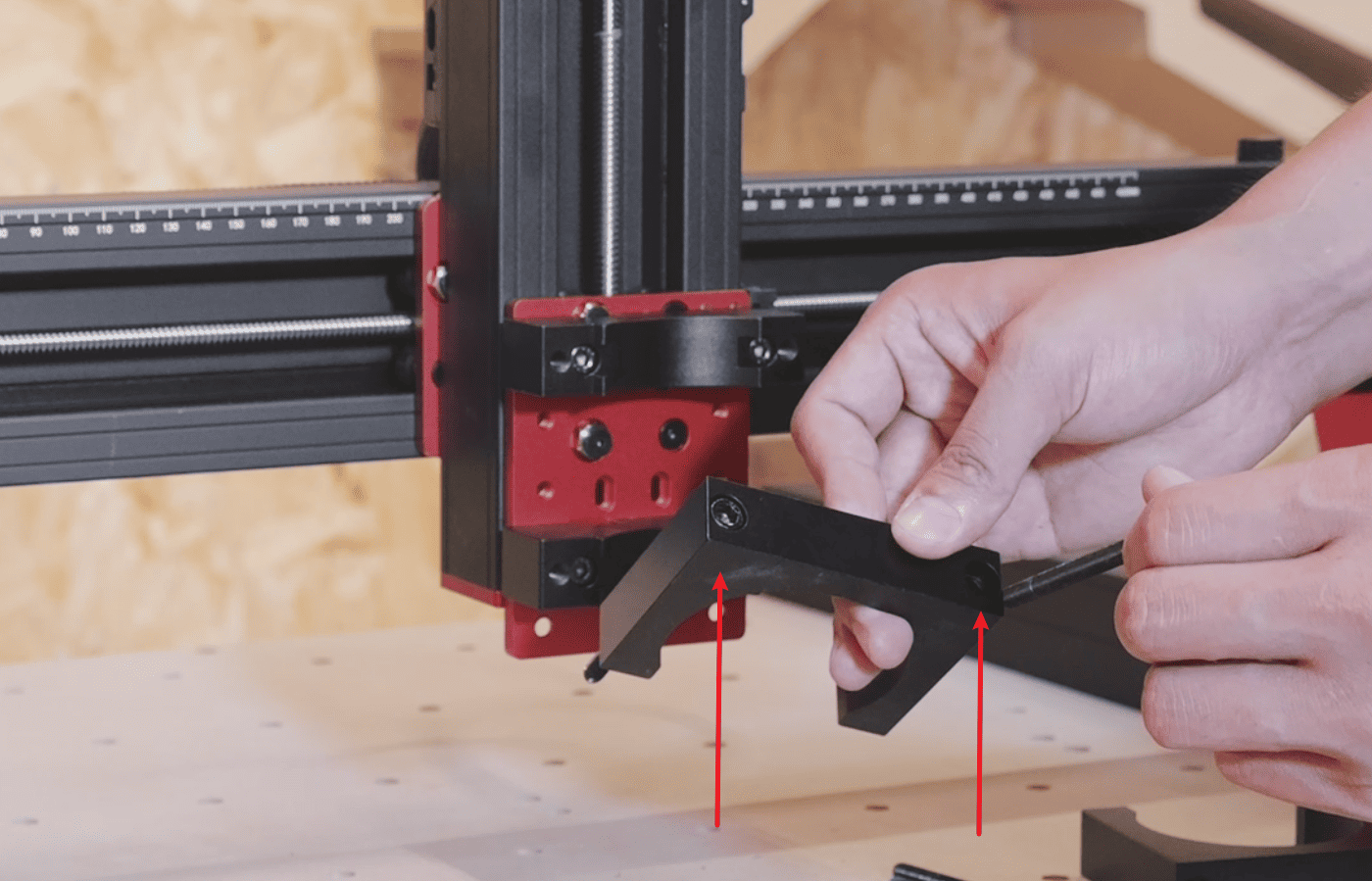
3.Loosen the four fixing screws of the protective backplate, remove the backplate, find the fixture base of the F65A spindle and align it with the threaded protrusion of the pulley.(Note: The groove on the base needs to align with the protrusion of the nut on the Z-axis slide to install it.)
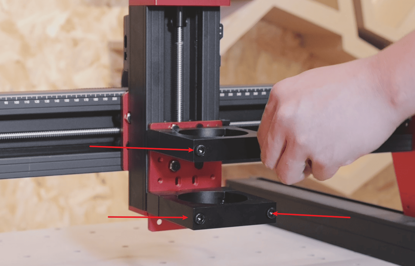
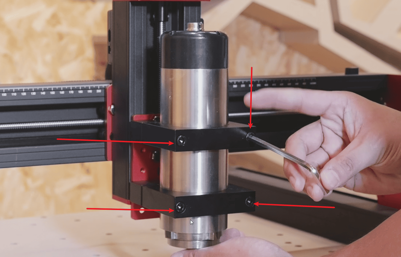
4.After securing the base of the fixture, remove the fixture that holds the spindle and pass it through the tightening screws.(Note: Do not tighten yet)
5.First, tighten the fastening screws of the spindle fixture slightly but not completely. Then, remove the F65A shaft and pass it through the fixture.
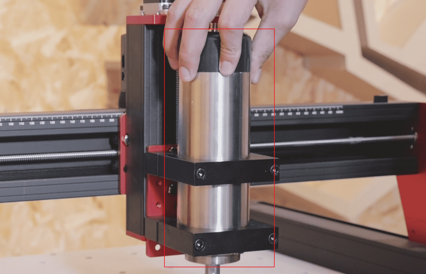
6.Just fix the tightening screws of the fixture to complete the installation of the spindle.
|
¶ Cabling installation
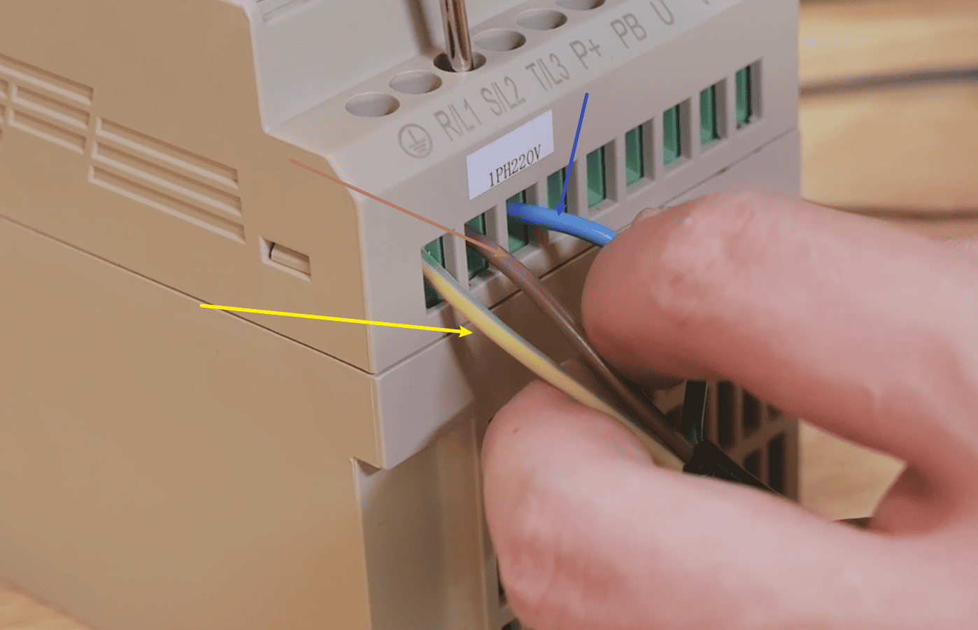
1.There are a total of three wires for the power supply. The yellow one is the ground wire. Connect it to the ground wire interface according to the ground wire marking. The remaining two wires, without any polarity distinction, can be directly connected to the R/L1 and S/L2 interfaces respectively.
|
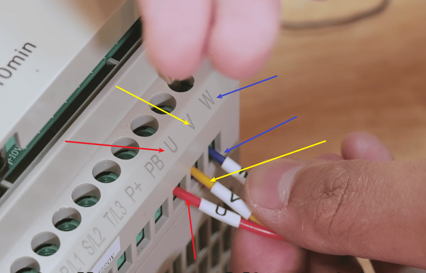
2.The main shaft control lines consist of three, namely U-V-W. The wire harness is marked with lines and can be simply connected to the corresponding interface of the frequency converter.
|
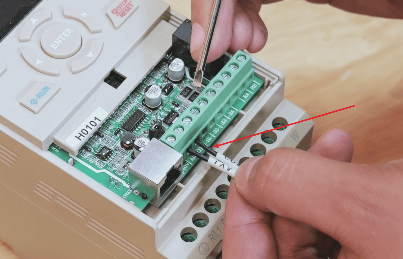
3.Open the cover of the frequency converter and locate the AVI and COM interfaces.
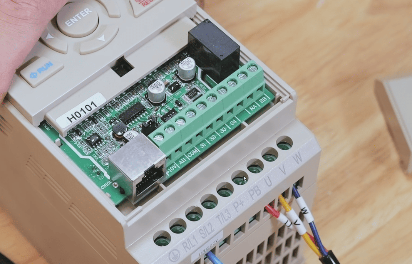
|
4.Connect the AVI and COM lines of the frequency conversion control cable to the corresponding interfaces.
|
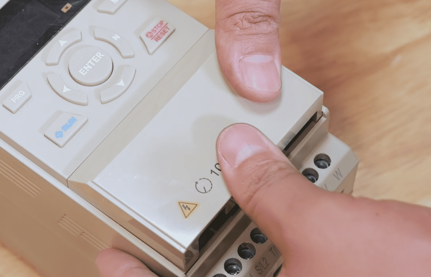
5.Re-close the upper cover of the frequency converter
|
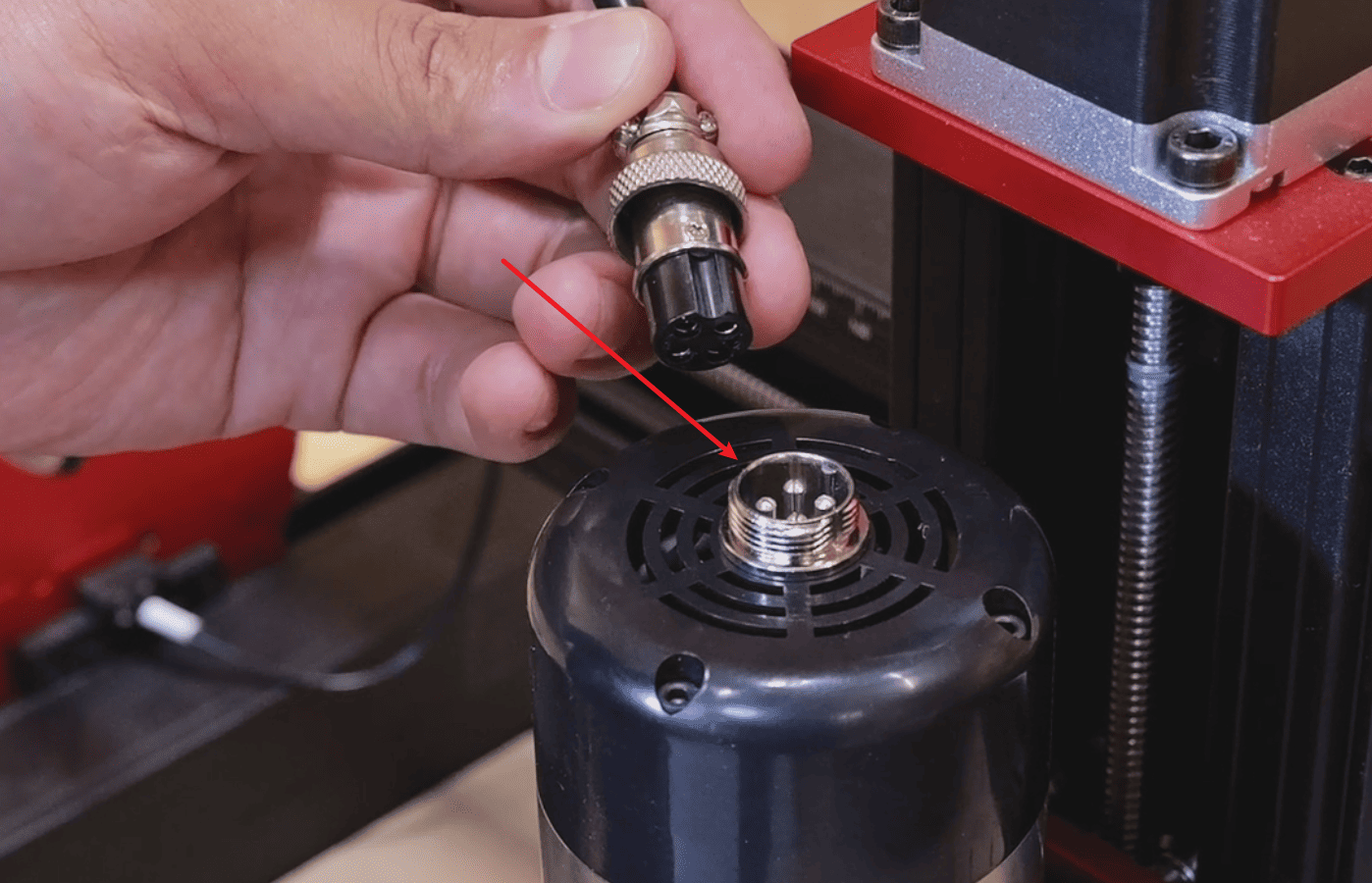
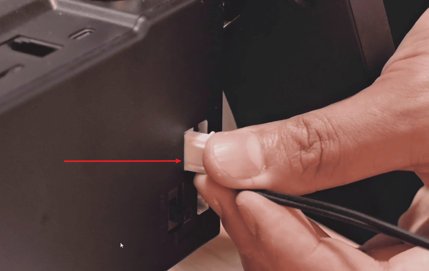
6.Connect the other end of the spindle control cable to the spindle connector.
|
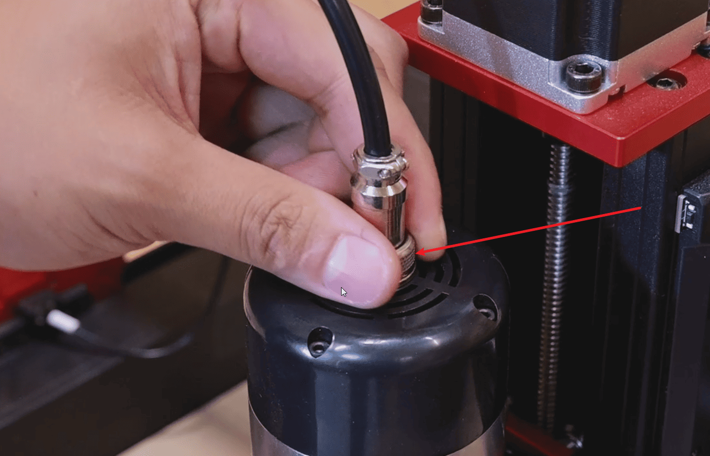
7.Fasten the fixing nut of the aviation plug firmly
|
8.Just connect the frequency control line to the VDF interface of the machine control box, and all the wiring can be completed.(Note: The 450Pro old version cannot use this function.)
|
¶ Start the main shaft
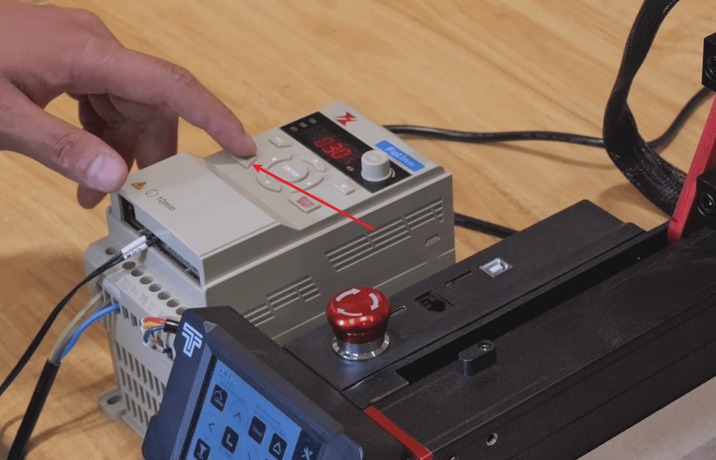
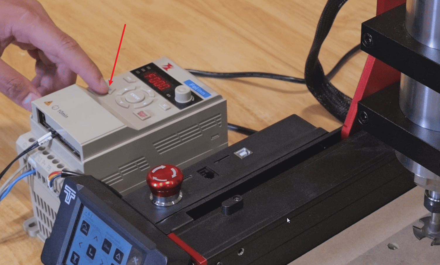
The F65A spindle has two startup methods: manual spindle startup and screen-based startup. However, in both cases, the “RUN” button on the frequency converter must be pressed before starting.
¶ Manual start-up
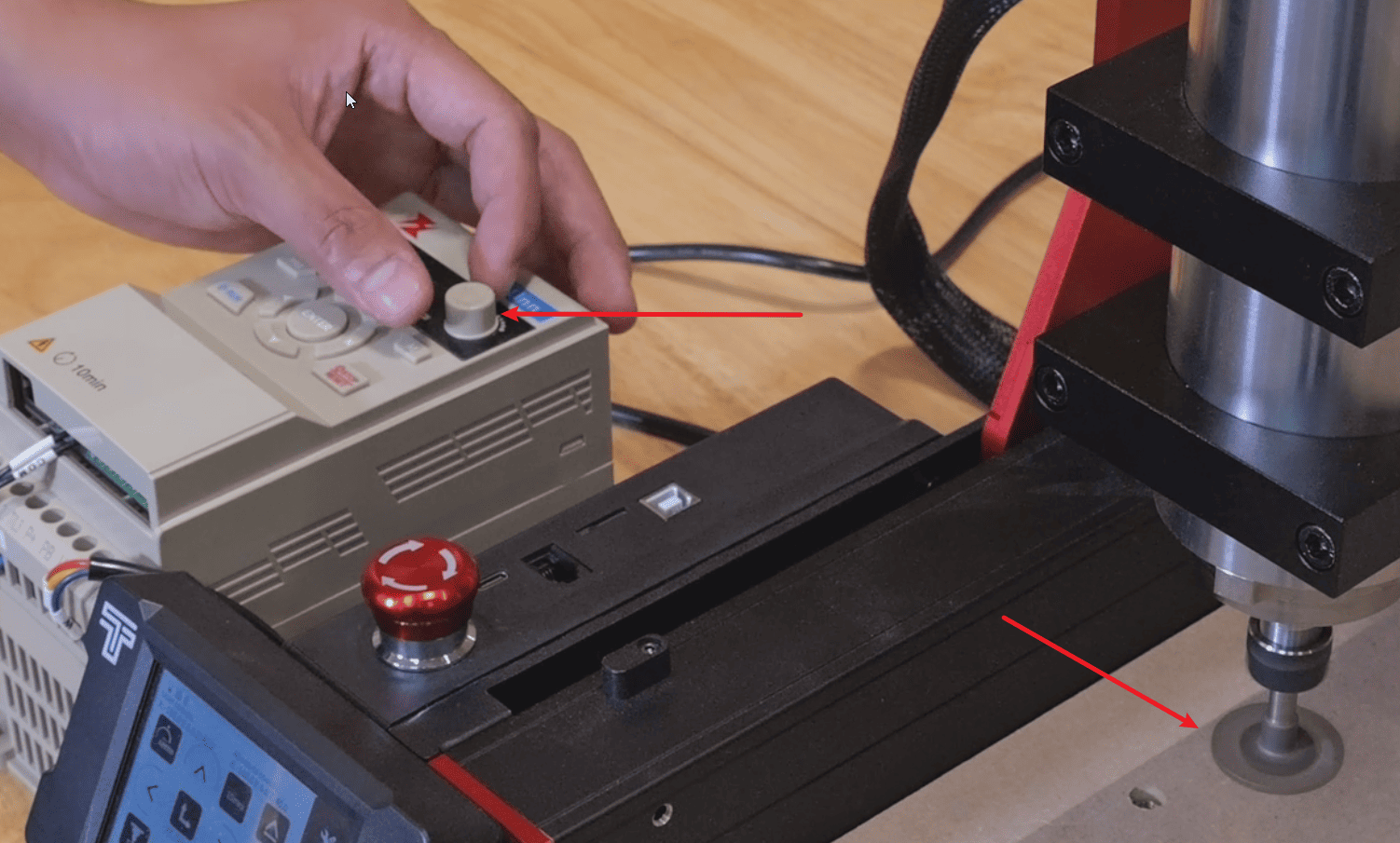
1.Press the RUN button and rotate the speed regulator to adjust the spindle speed.
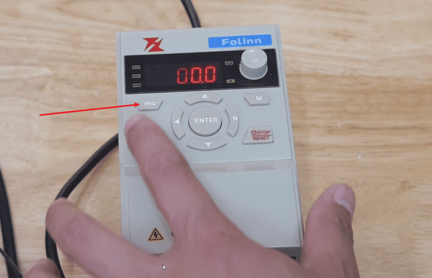
¶ Screen startup
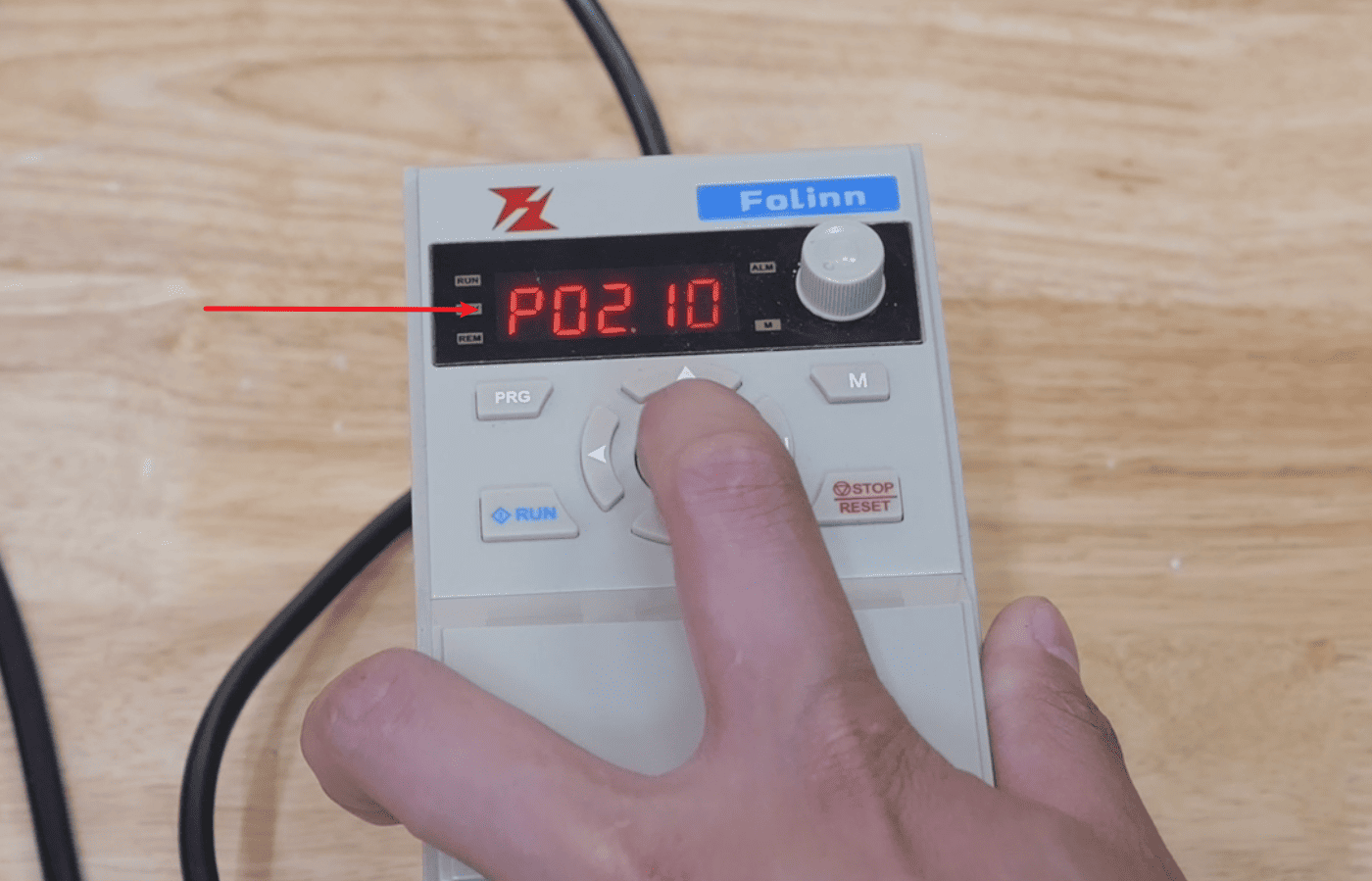
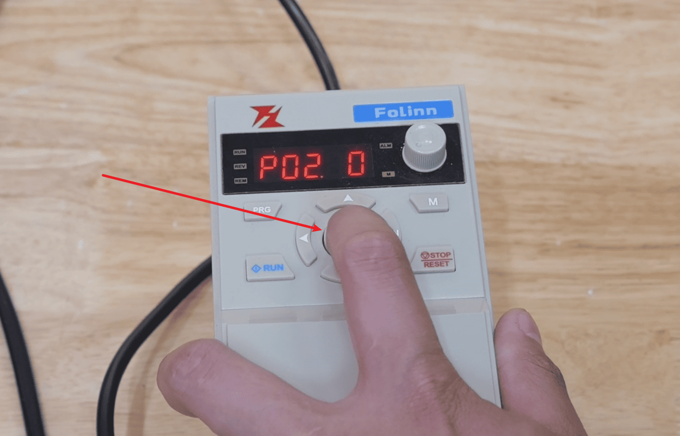
1.Press the PRG button to enter the programming interface and adjust it to P02.10.
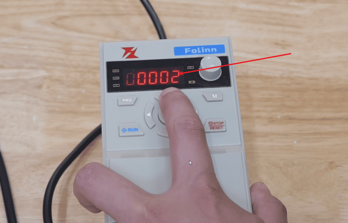
2.Press “ENTEP” to enter the next line and adjust it to 00002.
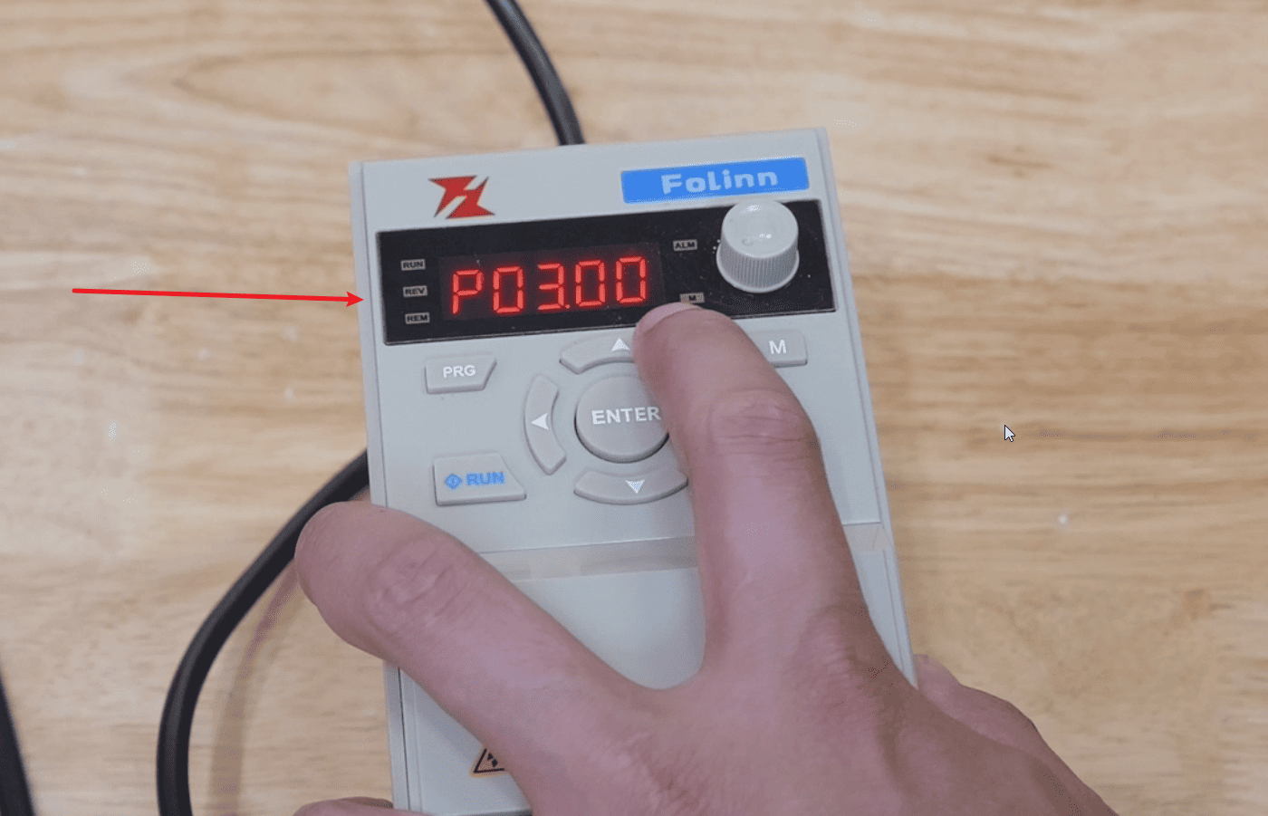
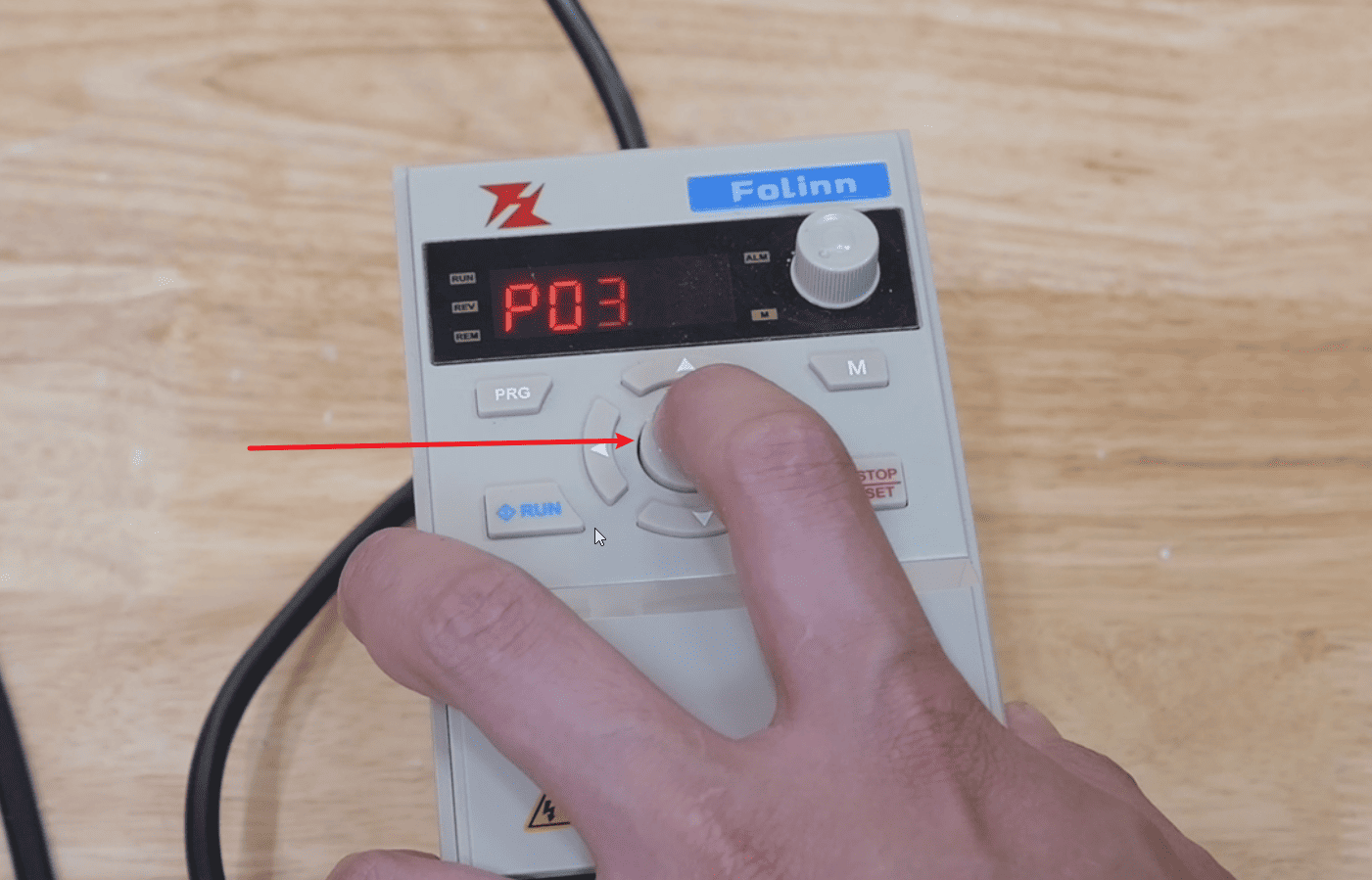
3.Press the “ENTEP” button to enter the next line and adjust it to “P03.00”.
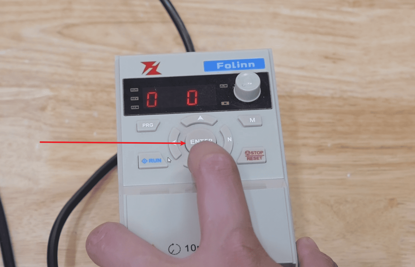
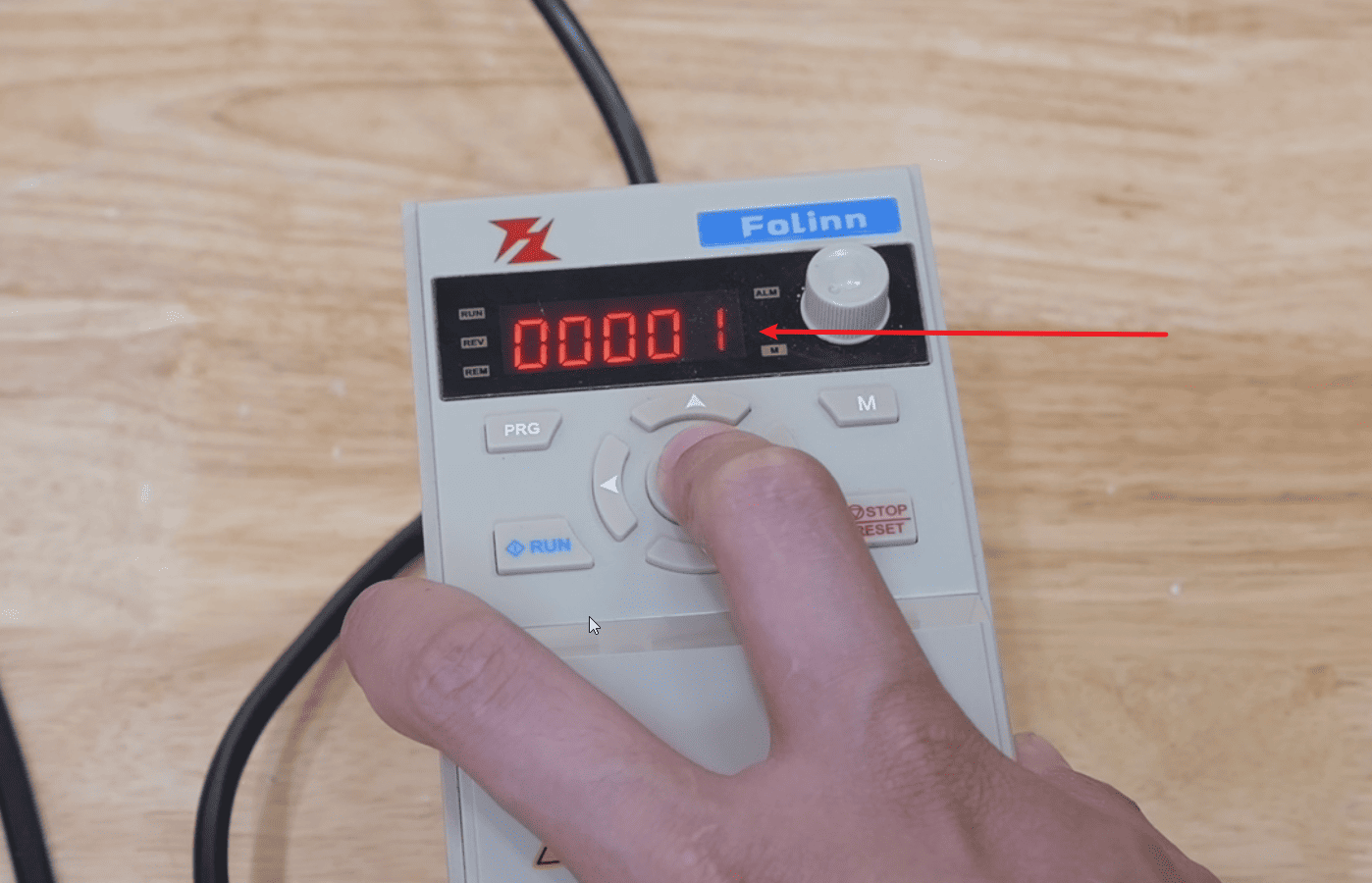
4.Press ENTP to enter the next line and adjust it to 00001. Then press ENTP to complete the debugging.
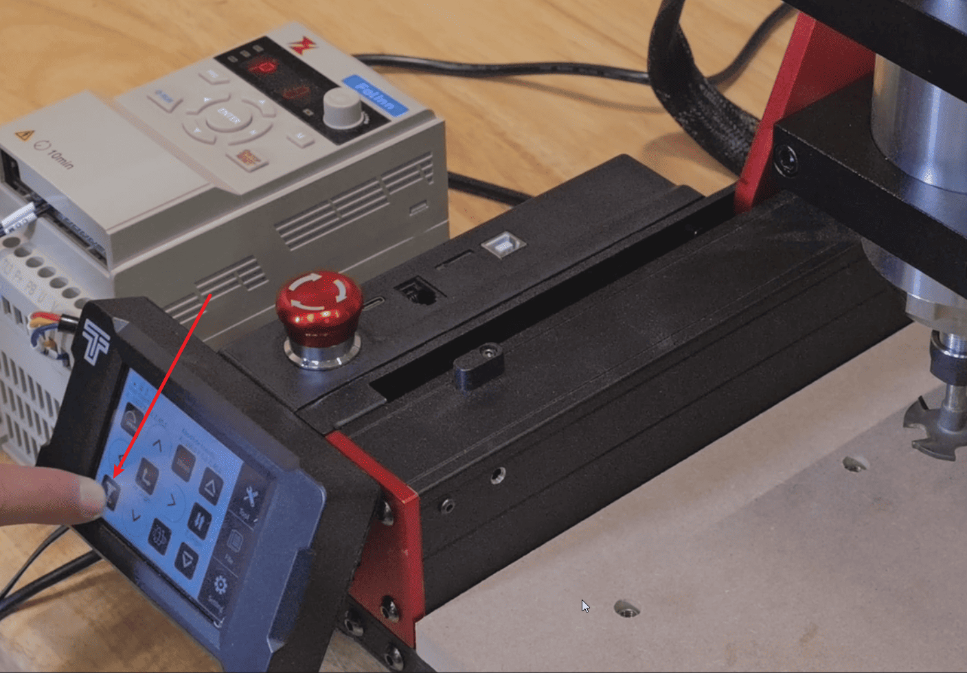
5.Click on “RUN” and then click on the spindle on the screen to start the spindle and open it.