¶ Instructions for Pulse Setting(Numerical Calculation)
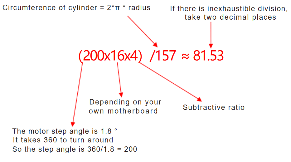
Pulse calculation formula: (pulse number of motor in one turn x driving subdivision x subtraction ratio)/cylinder circumference The number of pulses in one cycle of the motor contained in the kit: 200; Subtraction ratio: 4: 1
Example: The number of pulses and the subtraction ratio of the motor are fixed,and the number of pulses of the motor is 200. The subtraction ratio is 4: 1. Take TTC450 motherboard as an example. Thediameter of the cylinder is 50mm. So (200x16x4)/157 ≈ 81.53. The pulse number is 81.53.
¶ Instructions for Pulse Setting(Software)
Modify the pulse with CANDLE control software.
Step 1: Connect the machine.
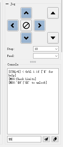
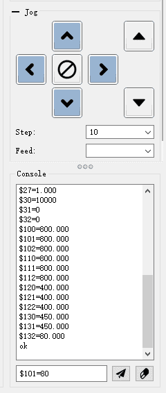
Step 2: Enter the $$symbol in the lower right corner of the software and call the machine parameters.
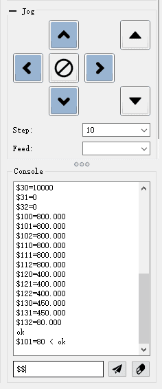
Step 3: Enter $101 = 80 and click Send.
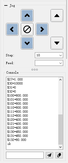
Step 3: Enter the $$symbol again to see if the change is complete. If the parameter changes, the change is successful.
 |
 |
 |
 |
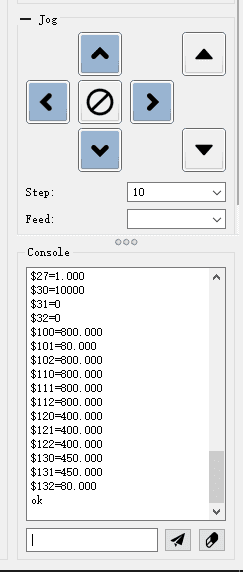 |
Note: The example in the picture is the Y-axis, $100 is the X-axis pulse, and $101 is the Y-axis pulse.
¶ Fourth-Axis Programming Tutorial
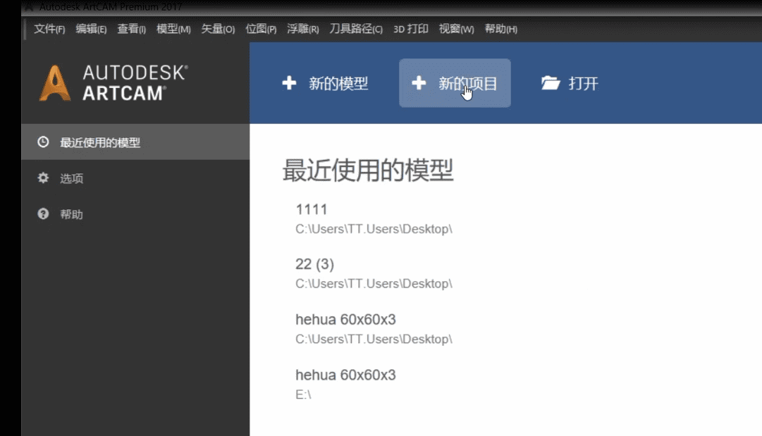
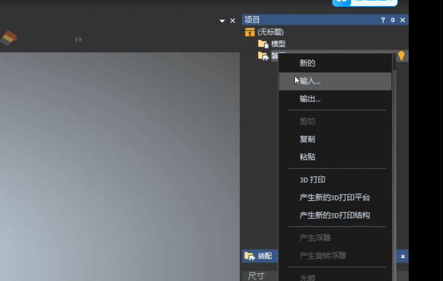
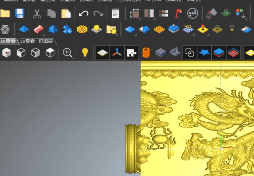
1.Open the ARTCAM software, select to create a new project, and then right-click on the model to choose to input the model.
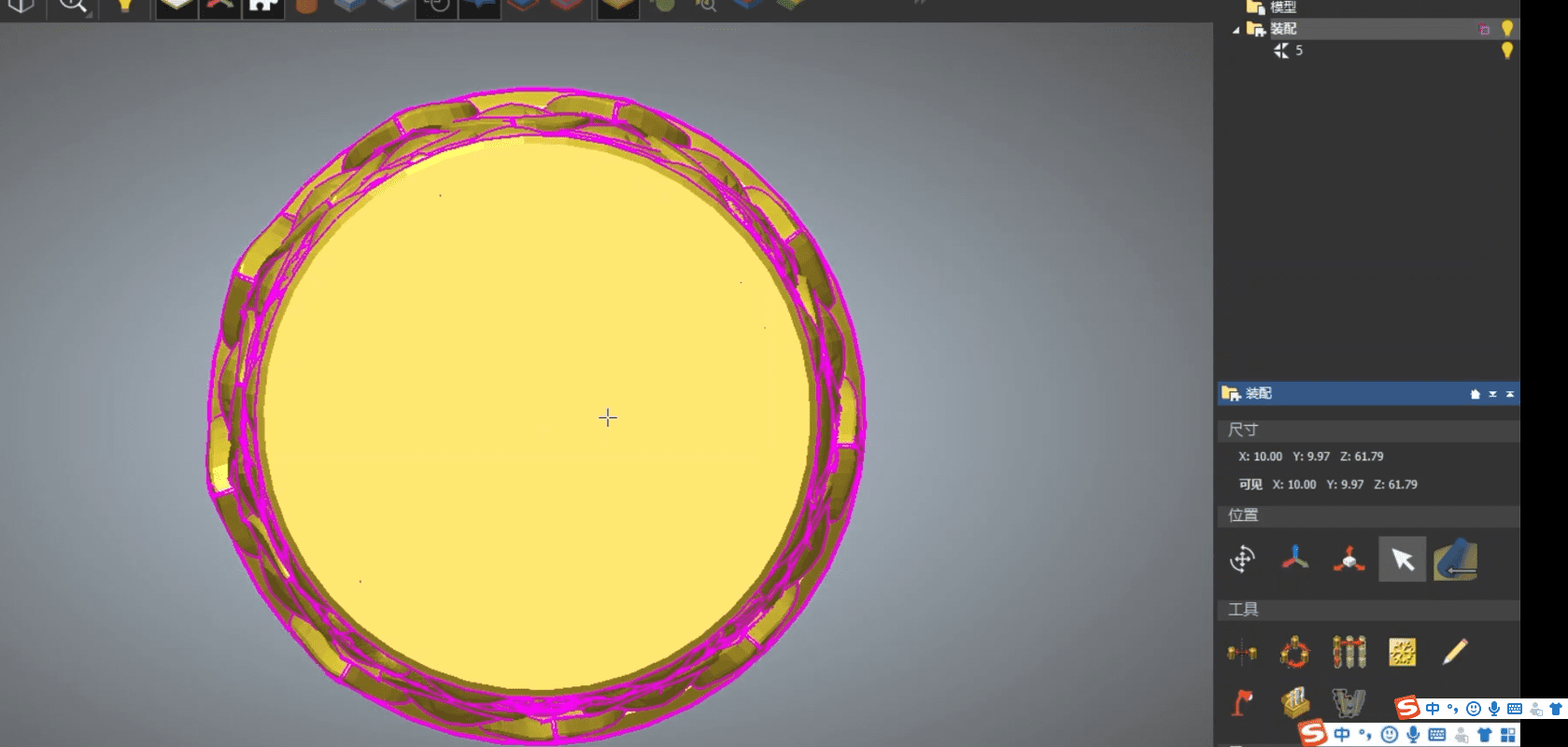
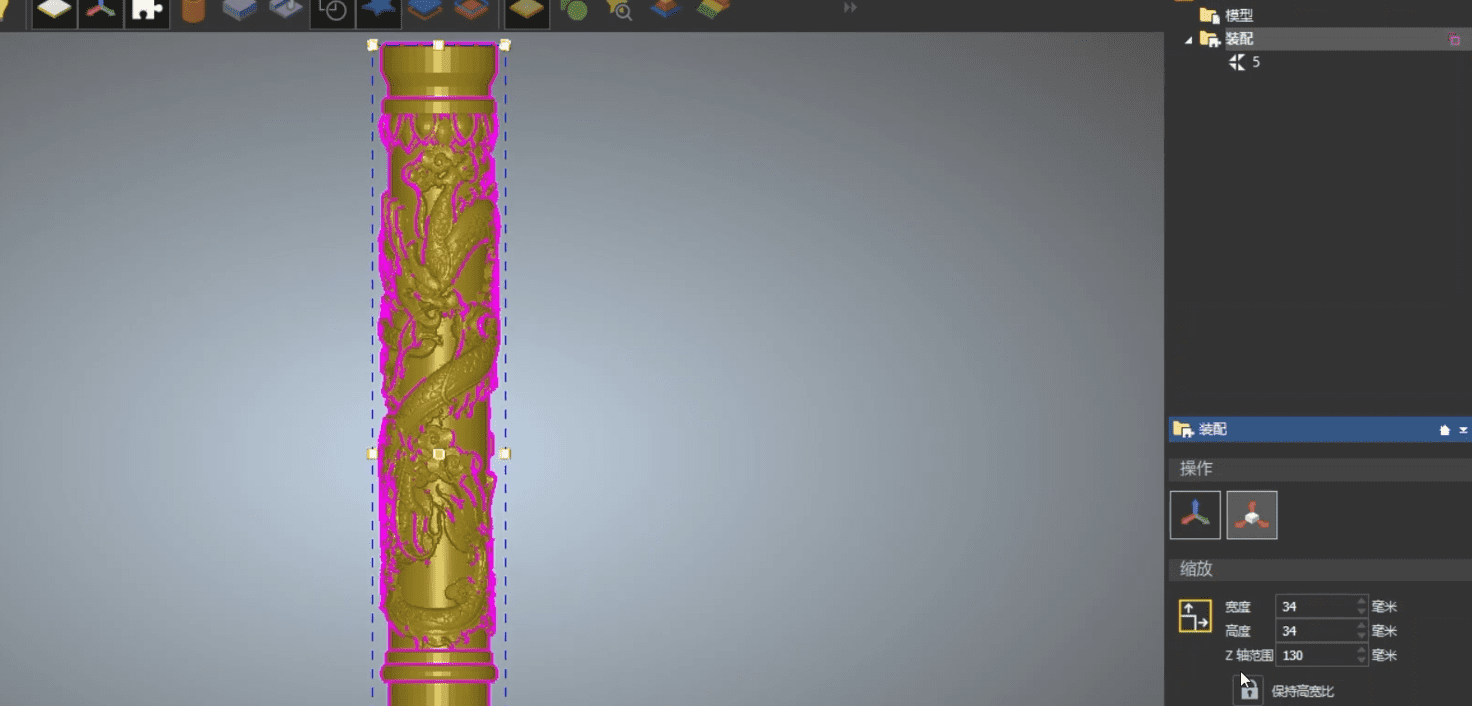
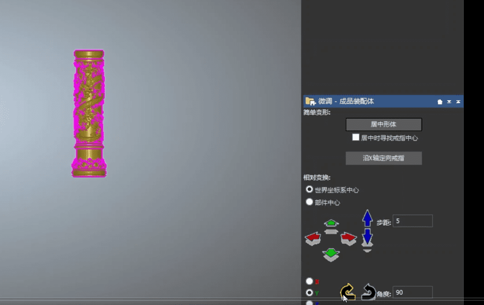
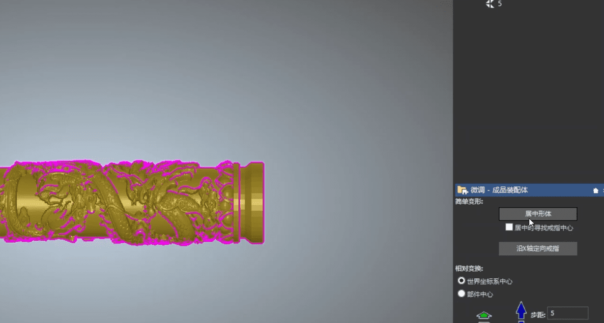
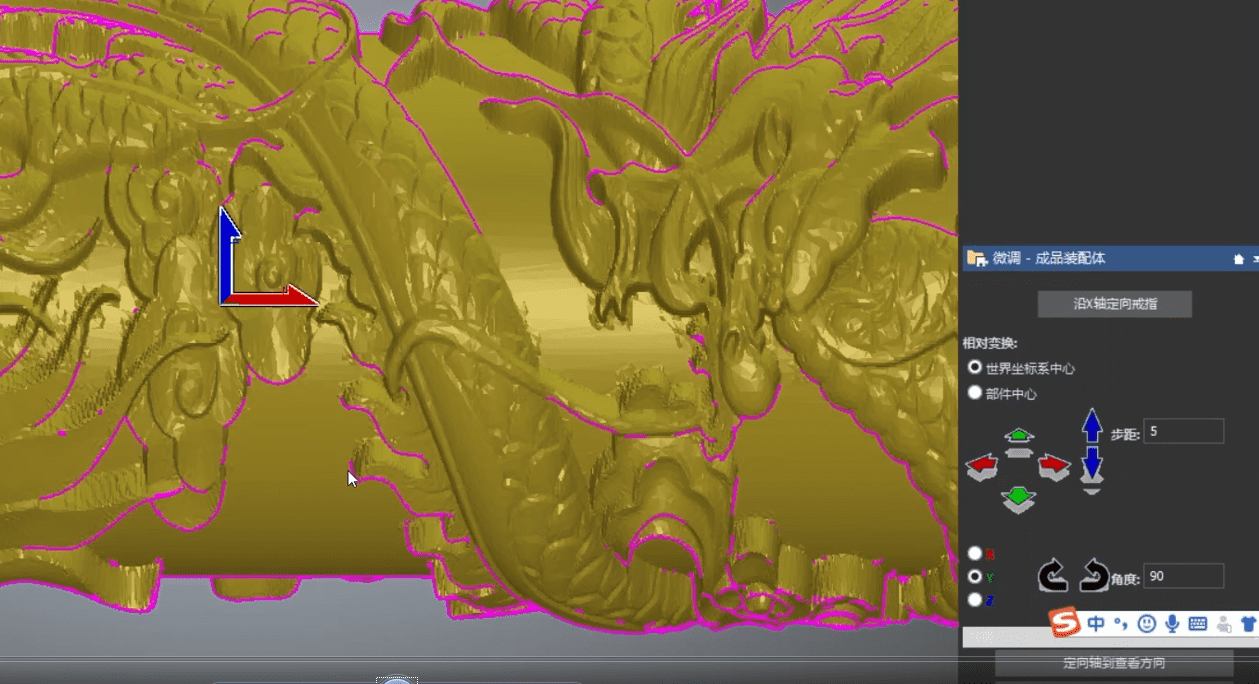
2.View the part in the front view, change the width and height to the diameter of the material you want to carve, and set the Z-axis to the length you want (note to reserve space for the clamp and punch), open the fine-tuning centering tool, select 90 degrees to adjust the position of the part, and then set the world coordinate system center.
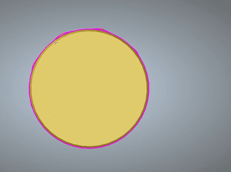
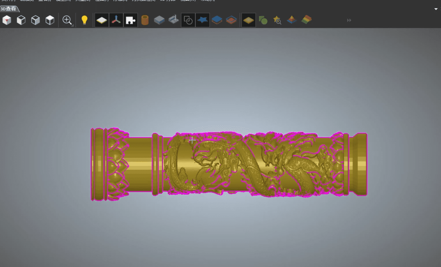
3.Check if the part’s position is normal. (Since it is usually rotated along the X-axis, it needs to be unfolded along the X-axis line) X is the base of the part, Y is the front of the part, and Z is the top view.
4.Check if the centered shape and the world coordinate system are at the center.
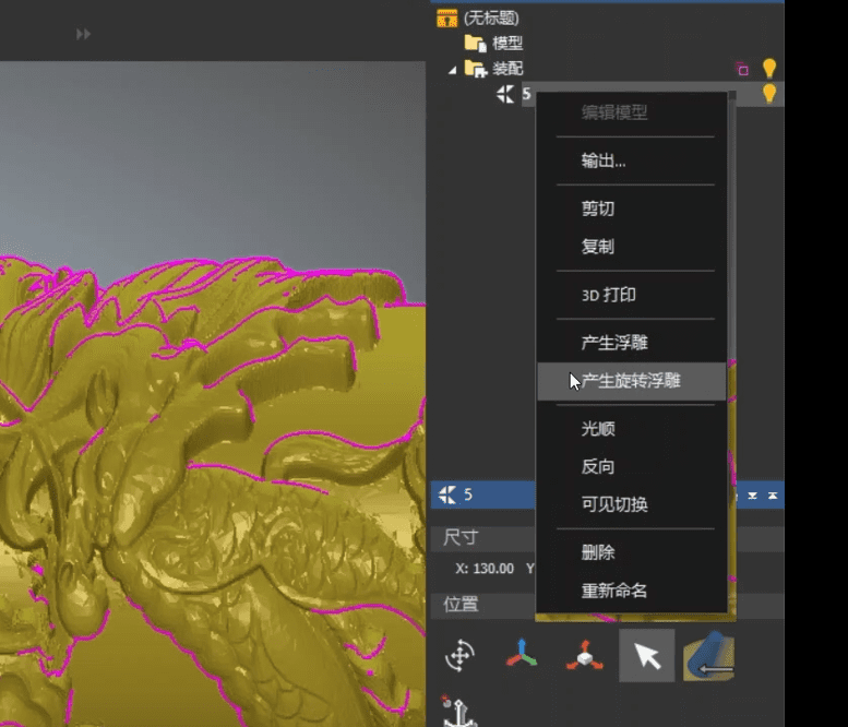
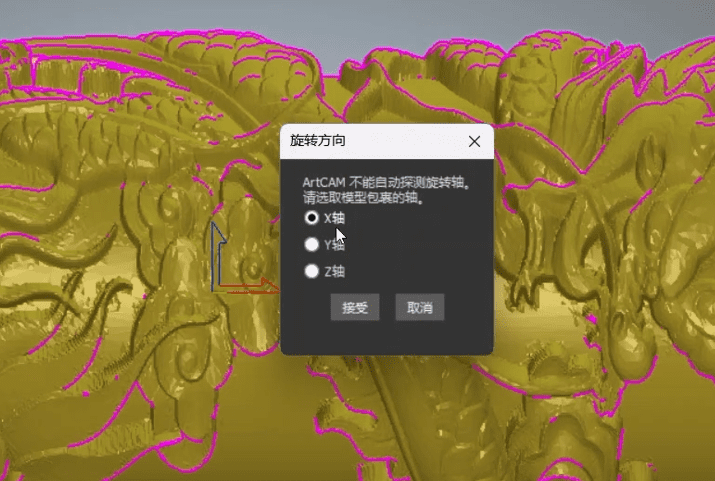
5.Right-click on the model option again, select to create a rotating relief, and choose to rotate along the X-axis.
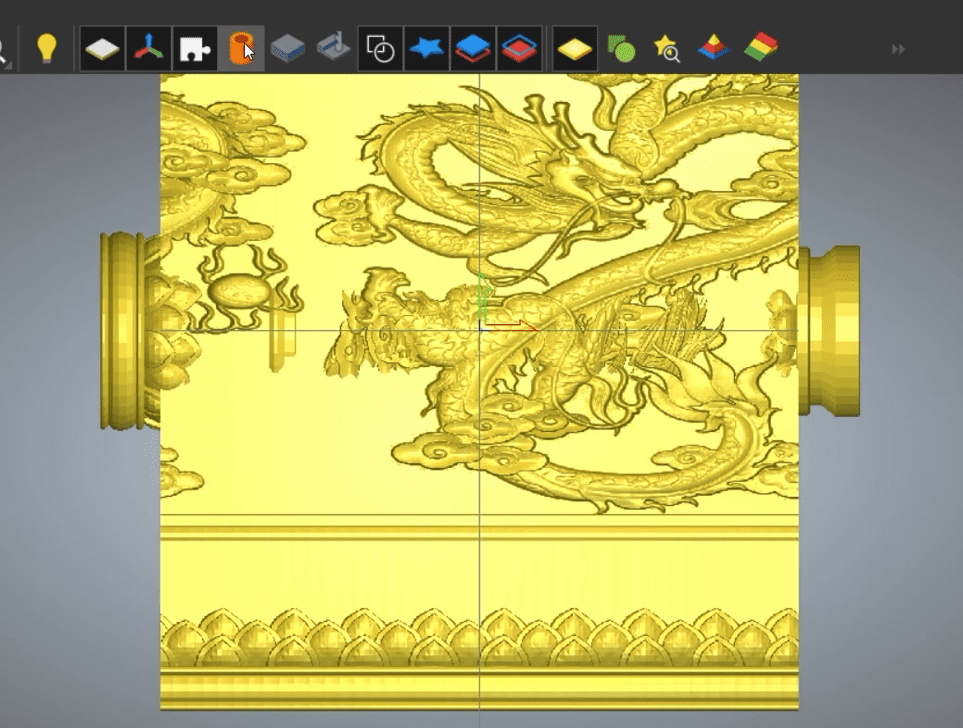
6.Switch to rotation to unfold the model, and click to switch the visibility of the assembly.
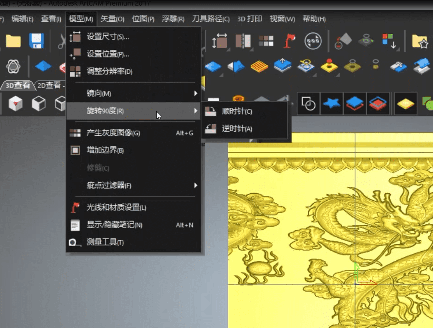
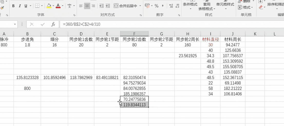
7.Click on the model option, select the model at 90 degrees, open the transmission calculation, input the material diameter, calculate the circumference and pulses.
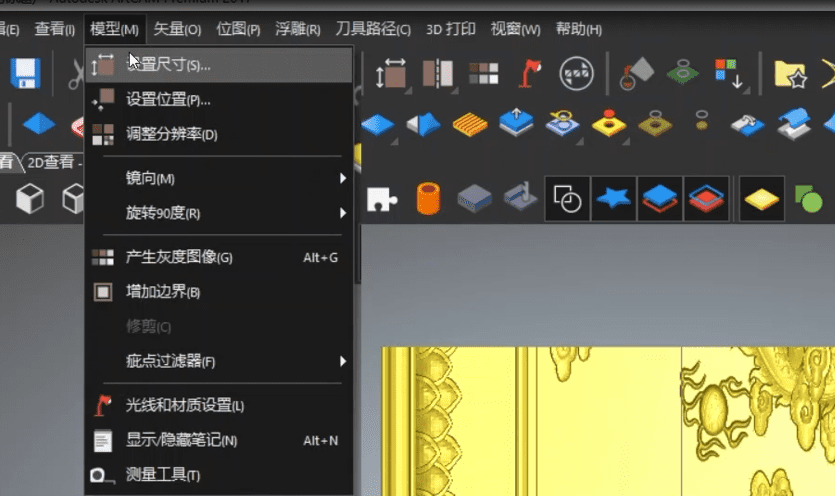
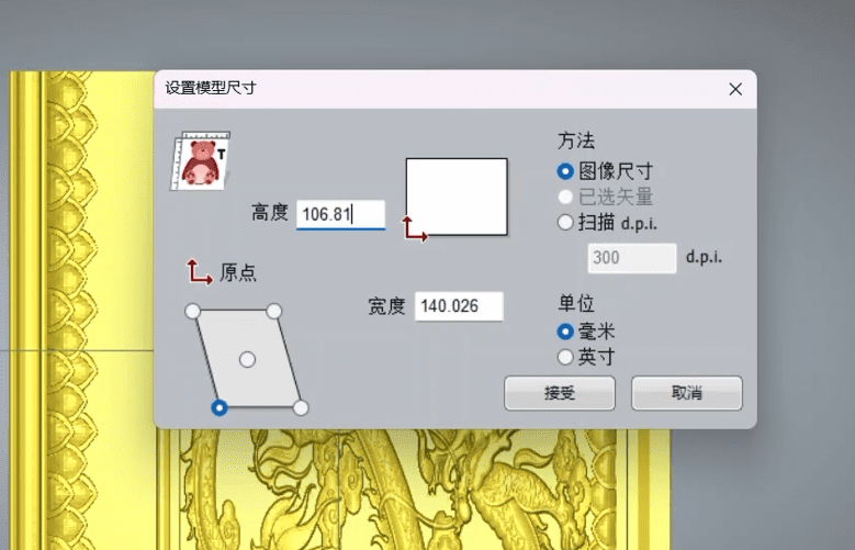
8.Open the model options, set the dimensions, and change the height to the calculated circumference of the material.
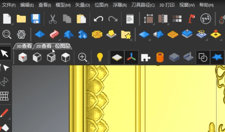
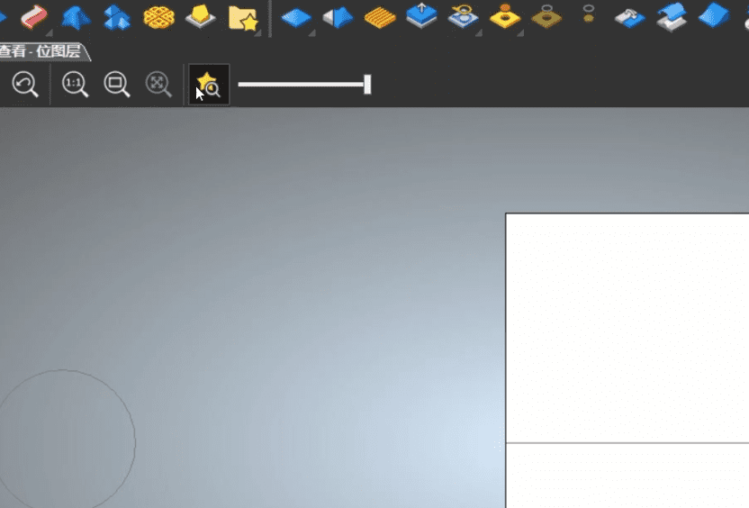
9.View the 2D layer and click on relief preview.
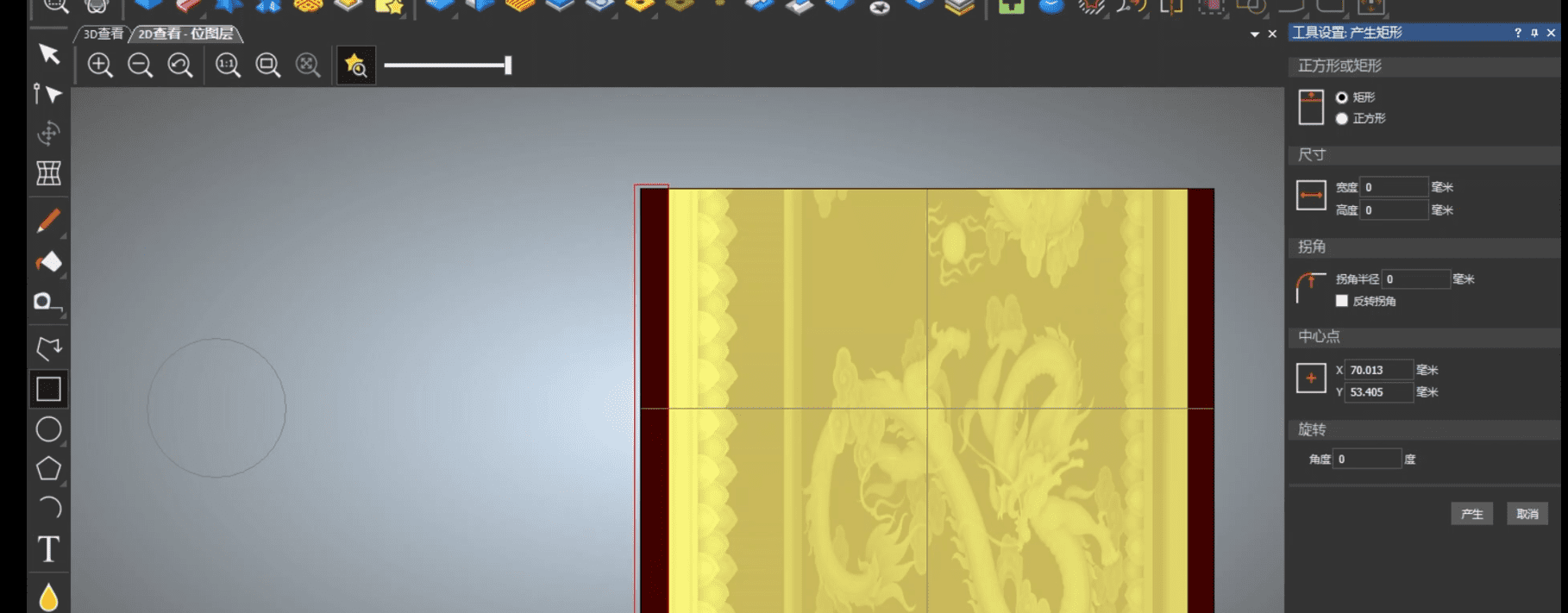
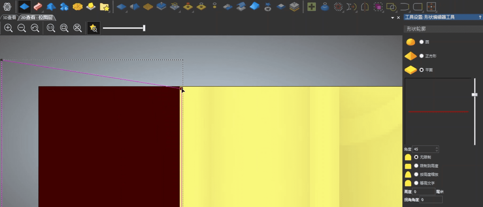
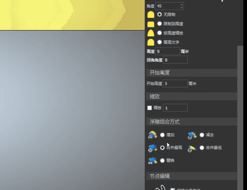
10.Select the rectangle as the connecting column for the relief ends, set the starting height (here it is the radius), merge to the highest point, and then generate it。
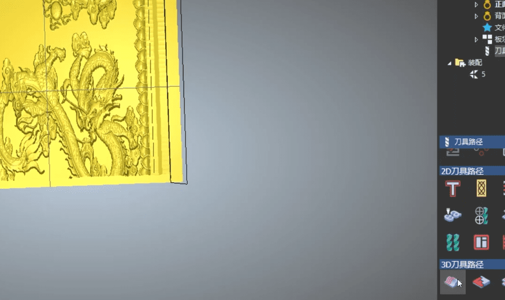
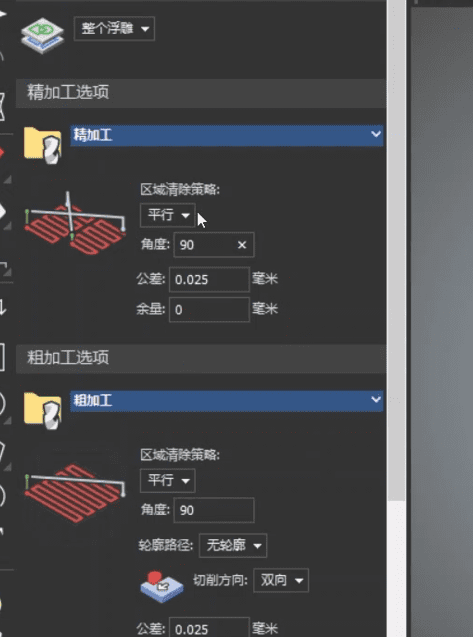
11.Right-click on the tool path, select 3D relief path, choose the tools for roughing and finishing, select the angle based on the wood grain, and set the safety height (recommended 5mm).
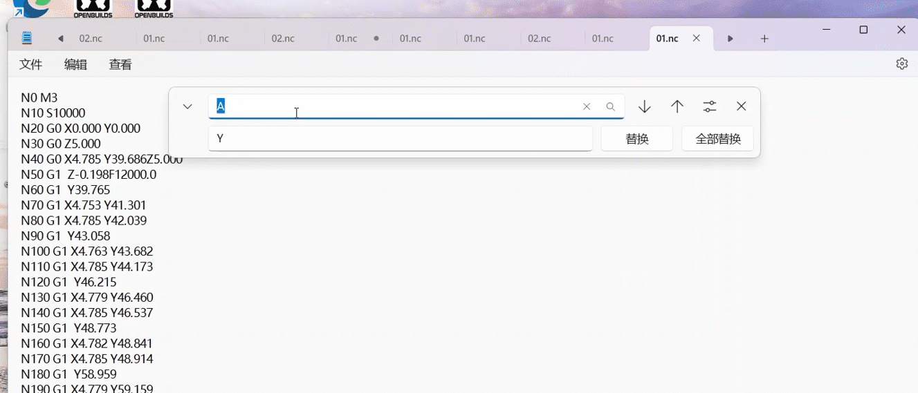
12.Save and exit. If you are using a TTC450 machine with the fourth axis placed horizontally, you do not need to change the G-code. If you are using a TTC450Pro model, which has an A-axis motor interface at the bottom of the screen, connect the fourth-axis motor cable and then open the G-code with a text editor, replacing all occurrences of “Y” with “A”.
|
