¶ Software installation
¶ How to install USB drivers?
Driver program name: CH340SER.EXE
Where can you find this program?
- It is included on the manufacturer’s TF card.
- Search on a browser: CH340SER or CH340 official website.
Note: Failure to install the driver program may result in the computer being unable to connect to the machine. The driver files for Windows and macOS are different.


¶ Carry out engraving

|
¶ Quickly understand the software
¶ candle
¶ Connect the software
1,Click on the second tool in the upper left corner of the software
2,Open the Settings of the sliding page

|
3,After opening the Settings, select the corresponding COM port for you and check if the baud rate is 115200. Then you can connect to the machine and software

|
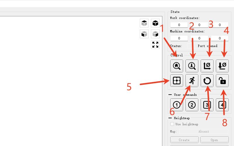
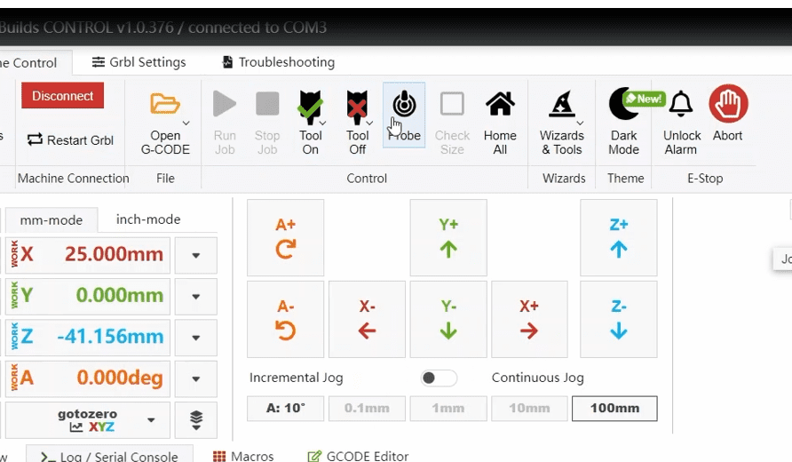
¶ Software Introduction (Explained in the order of the arrows
1,The home key is used to return to the mechanical origin of the machine and reset it to zero. (Note: Do not click on machines without limit switches.)
2,Probe is used for tool setting. After the tool setting block is installed, clicking this key can calibrate the Z-axis coordinates. (Note: Do not click this key when the tool setting block is not installed to avoid damaging the machine tool.)
3,After the tool setting is completed, this function allows you to click to reset the coordinates of XY and set the current position as the working origin
4,Z reset: This function can manually reset the coordinates of Z and can be used for manual tool setting when the tool setting block is not in use
5,Resetting the origin can quickly locate the working origin
6,The safety height function generally does not require operation when not in use
7,The reset operation can stop the movement while it is moving
8,Unlock, used to unlock the motor. After returning to zero, click to manually rotate the handwheel to move the shaft
|
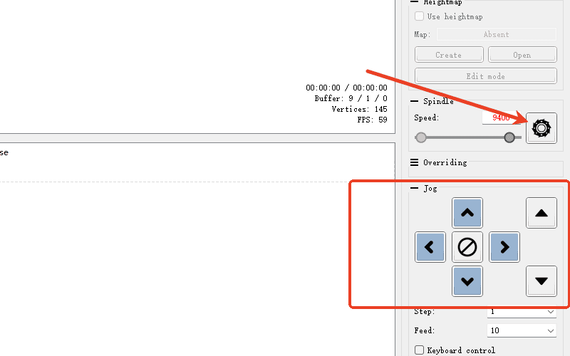
¶ Control interface
The arrow indicates the opening switch of the main shaft
The direction keys for the movement of the machine’s shaft are in the red box
|
¶ OpenBuildsCONTROL
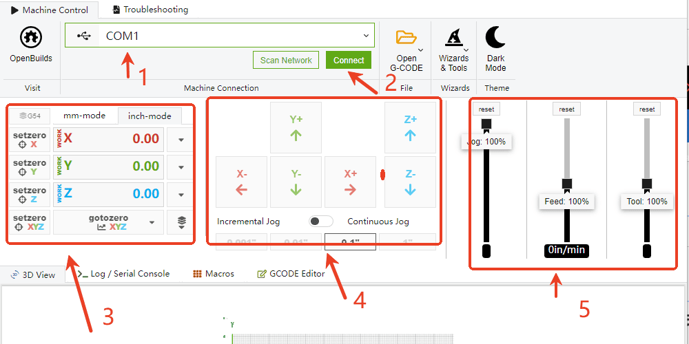
¶ Explain the functions of the common software functions as indicated by the arrows
1,Select the COM port. Here, choose the interface that your machine and software recognize. If you are not sure which one it is, you can first disconnect the connection line and see which com port is missing to get the correct interface
2,After finding the correct com port, click on it and you can connect to the machine
3,The current positions of all axes of the machine are shown in the red box. You can click the center symbol to reset it to zero
4,Here is the direction movement key of the machine. Click the corresponding arrow to move the corresponding axis
5,Here is to adjust the feed speed and acceleration of each axis of the machine, and the third one is to adjust the rotational speed of the main shaft
|
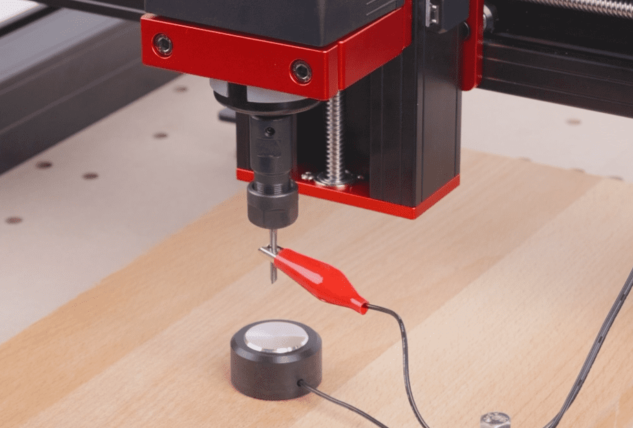
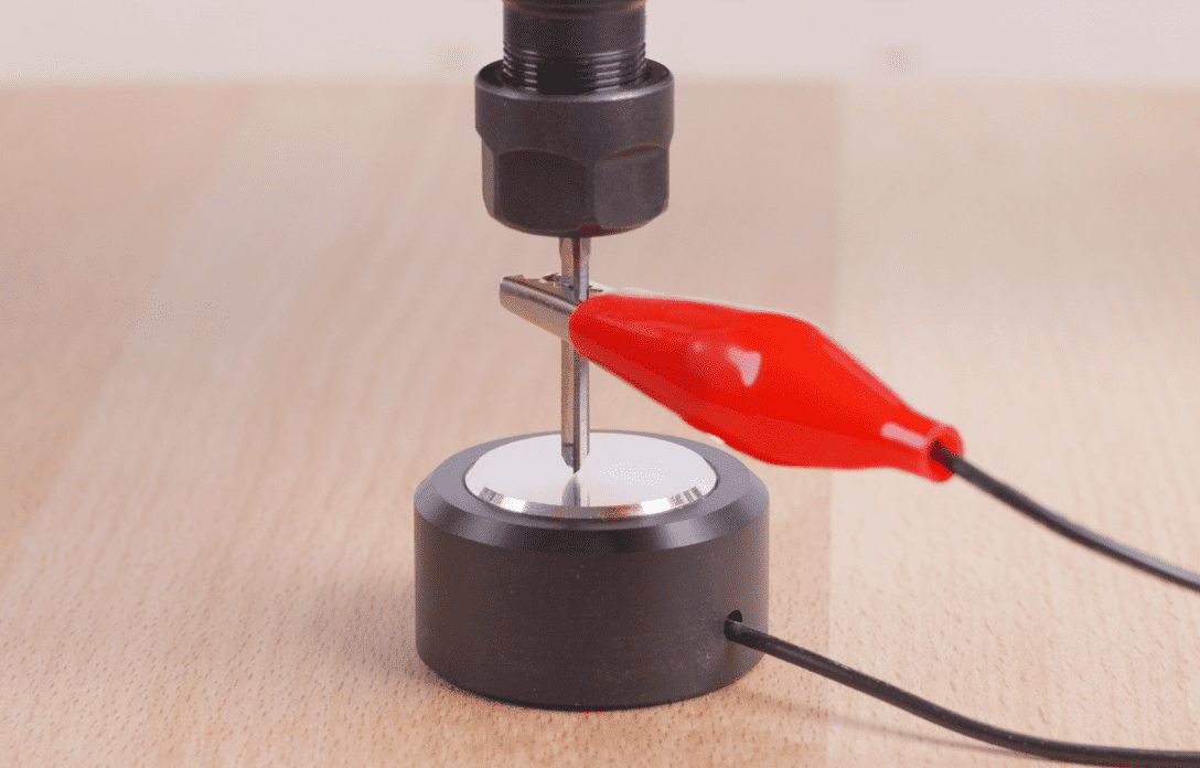
¶ Tool setting calibration
Software tool setting (In addition to using the tool setting method in the engraving tutorial, software tool setting can also be used)
¶ candle
1.Click on the software to connect the machine and set the tool setting command (G21 G91 G38.2Z-50F55; G0Z1; G38.2 Z - 2 f30; G92Z19. 5; G0Z5F10M30;) Where Z19.5 is the thickness of the tool block (if there is an error in the tool can be adjusted here)
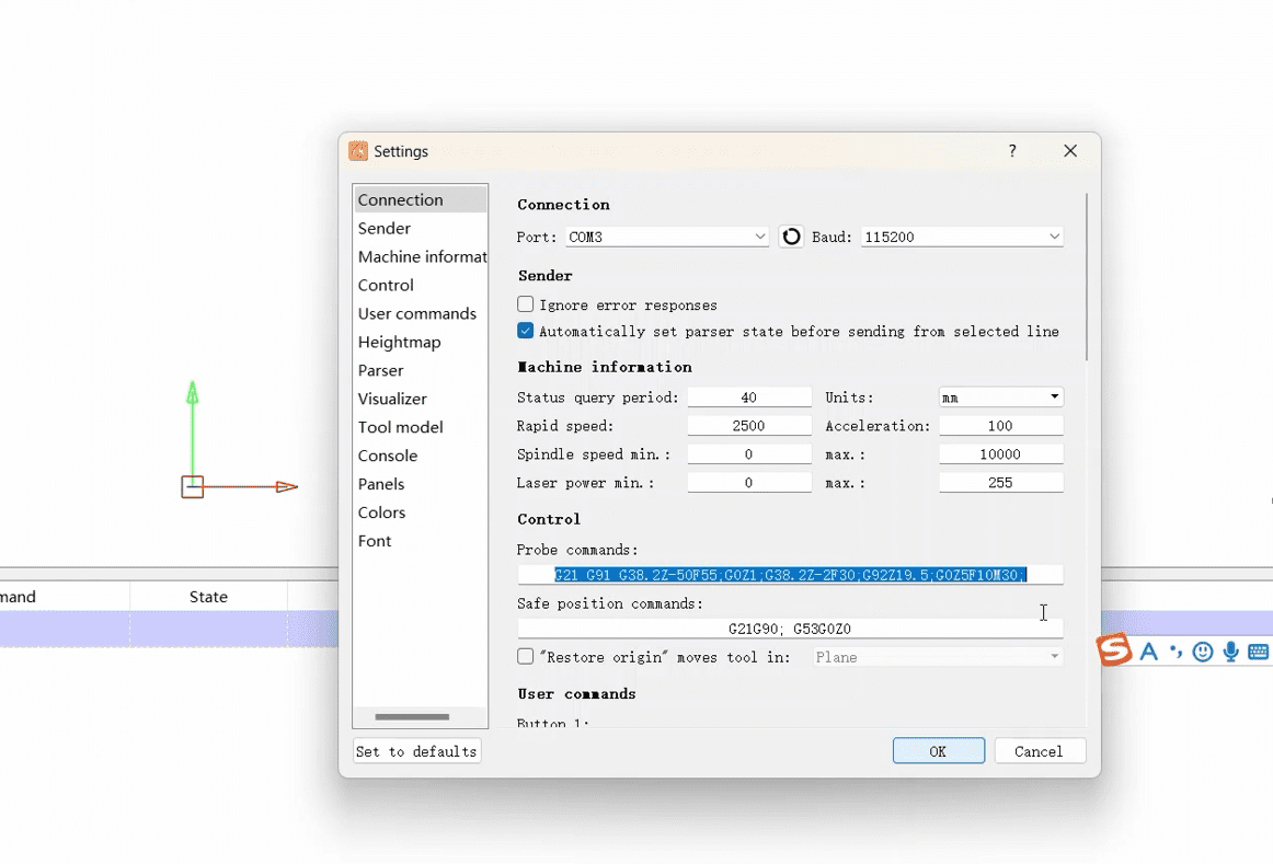
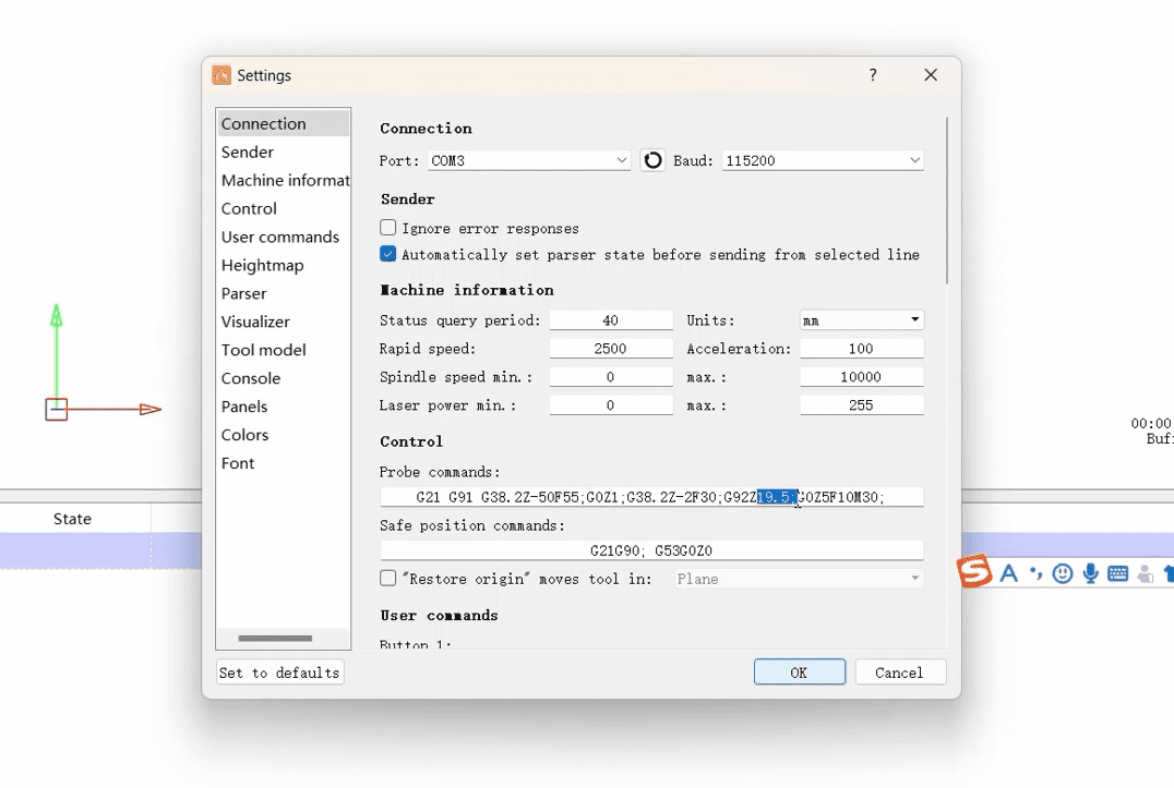
2.Then click Z Probe and wait for the knife to complete
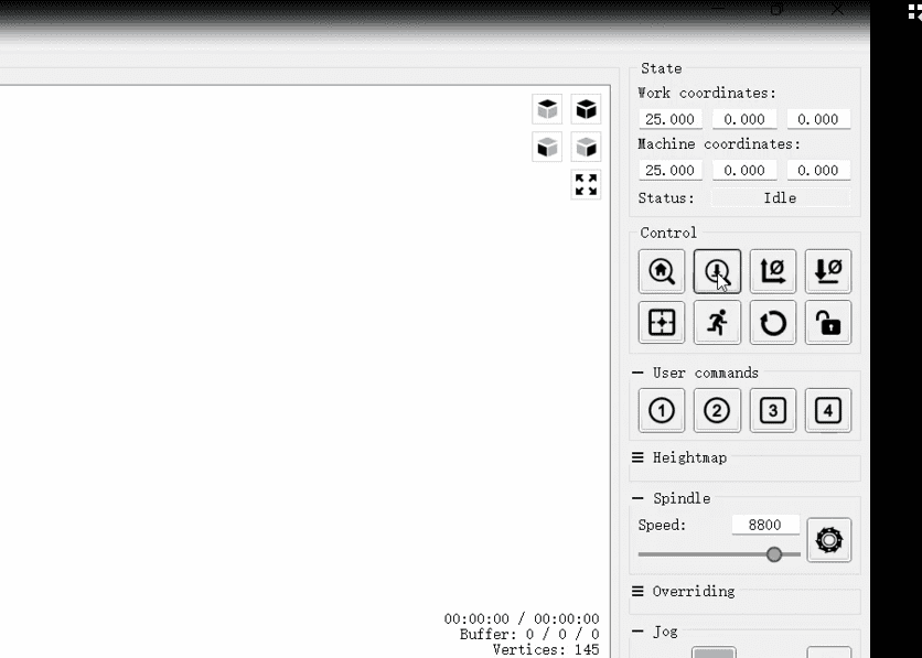
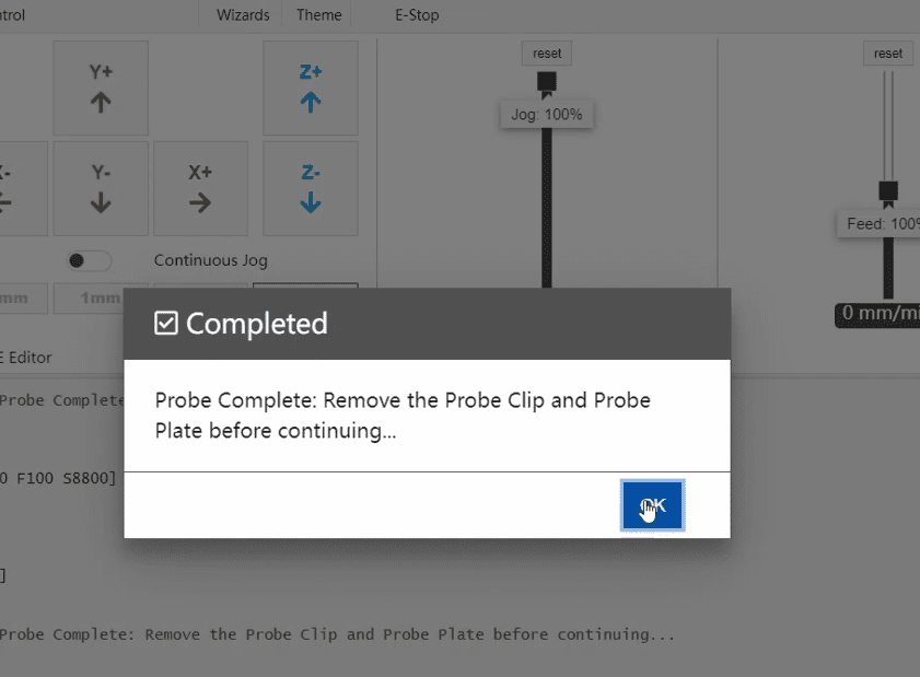
¶ OpenBuildsCONTROL
1.Open OpenBuildsCONTROL and click the Z probe. 19.5 in the pop-up interface is the thickness of the cutter block (if the cutter is deviated, you can adjust the thickness here).
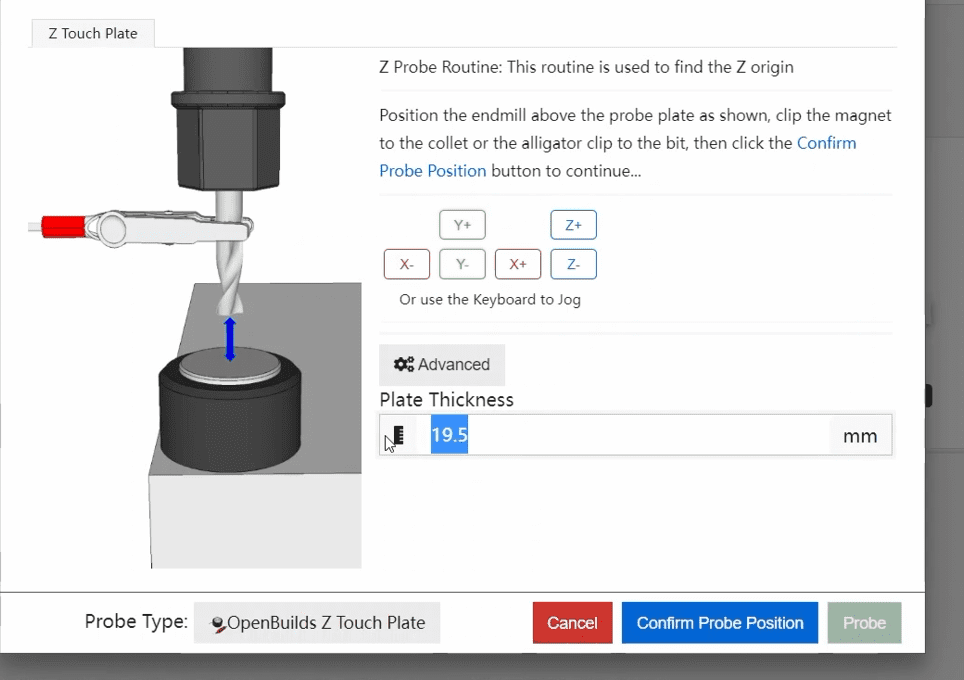
2.Then click Save and wait for the knife set to complete before clicking Probe
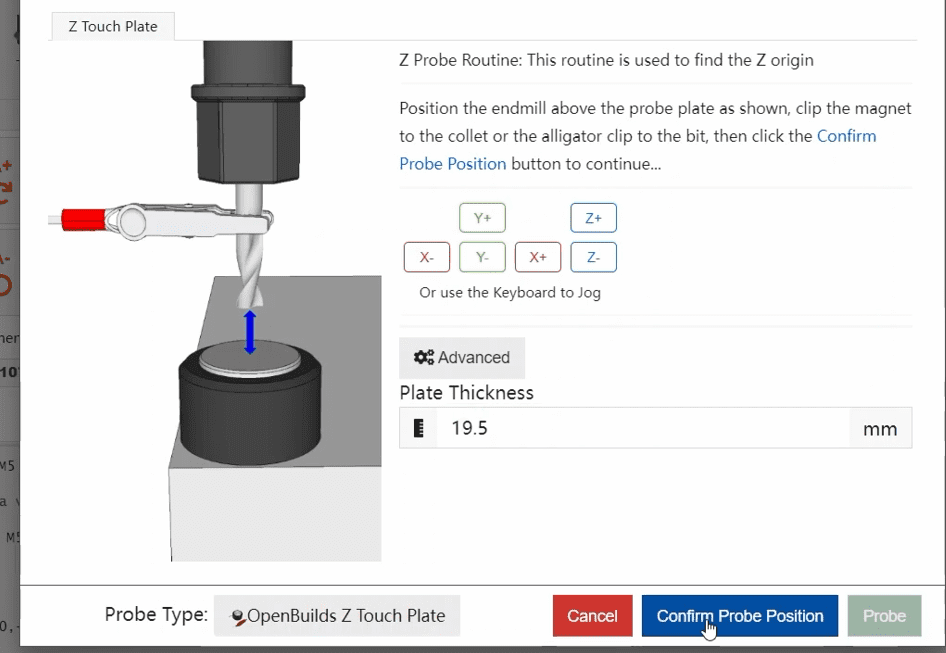
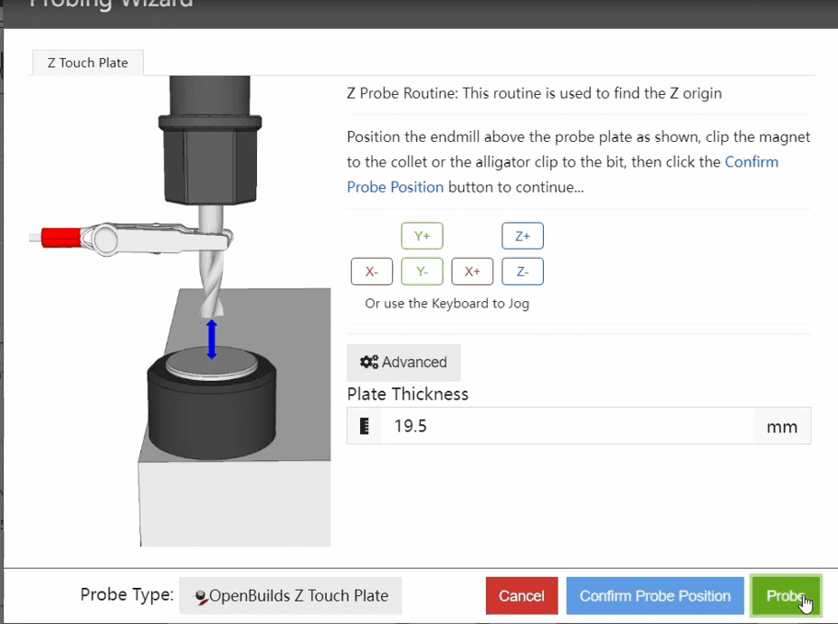
3.Click OK when the knife is finished