¶ Machine Cannot Connect to Computer, How to Handle?
- Ensure that the machine is turned on.
- Make sure the USB cable is connected to the machine’s port.
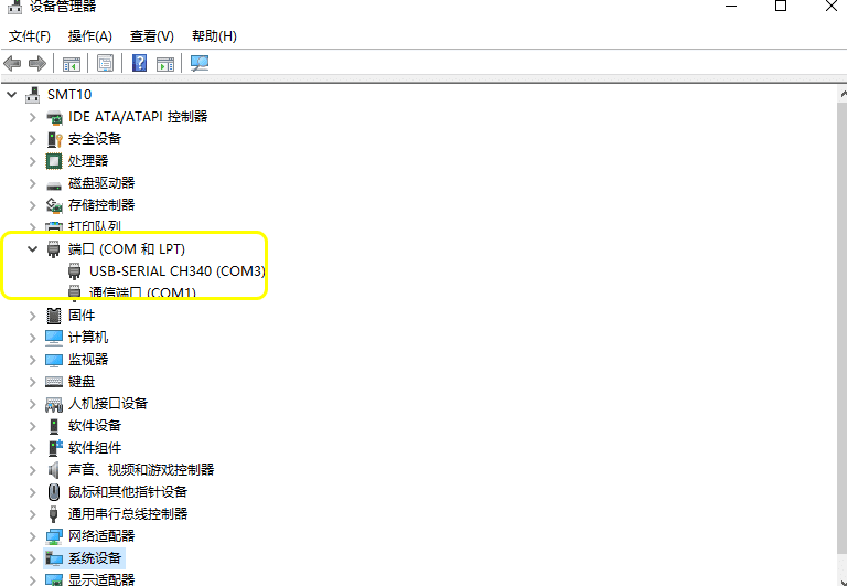
- Check if the computer can recognize the machine’s COM signal. (Or try plugging it into a different port on the computer)
- If no new COM is seen in the previous step, you need to install a CH340 driver. It can be obtained from the TF card files. Alternatively, install the CH340 driver through the LaserGRBL tools.
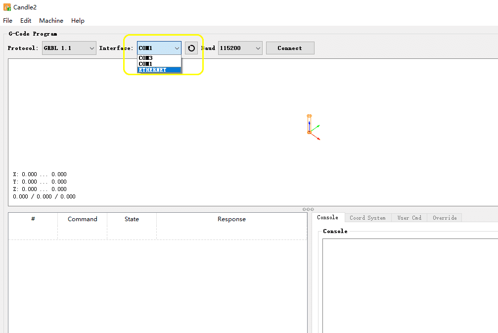
- Set the correct baud rate, 115200.
- Select the correct “COM” port in the software. (You can try every COM port)
- Click to connect.
- If the above steps still cannot connect, please restart your computer and then re-execute steps 5-7. (There may be software conflicts).
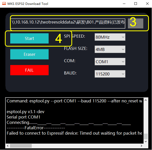
- If it still fails and there is a prompt message in the left dialog box of the software, you need to update the firmware. Then redo the above steps.
¶ Motor Does Not Work, How to Handle?
- Ensure that the machine has successfully connected to the computer’s Candle software. Because if it is not connected successfully, you cannot control the motor to operate.
- Check if the motor cables are correctly installed. (You can try reinstalling)
- If there is a motor that works normally, you can open the control box, find the main control board, and swap the motor cables inside the control box. If it still does not work after swapping, it indicates that there is a problem with the cables. Please inform us to replace them.
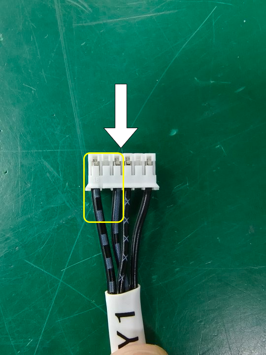
- If the motor vibrates but does not move, it may be that there is a problem with the sequence of the cables. You can use a tool with a sharp corner to swap the order of the two central wires.
- After swapping the order of the cables, if the direction is incorrect, you can swap the order of the two adjacent wires on the left.
- After checking step 3, if the originally normal motor also does not work, it may be that the driver of the main control board is damaged. Please inform us to replace it. When informing us, a video would be better, as it can facilitate us to better confirm the problem and replace the new parts.
|
¶ Machine Makes Unusual Noises, How to Handle?
It may be caused by the following two situations:
First Type
- Exceeding the machine’s working travel.
- Friction of the transmission parts.
Second Type
- Exceeding the machine’s working travel. Please try the following operations. Set the software parameters according to the machine’s nominal working size, the working range of TTC3018 is 300mmx180mm×40mm.
- Friction of the transmission parts. Please try the following operations.
2.1. Turn off the machine power, move the X-axis left and right, move the Y-axis front and back, and check for any jamming or difficulty in movement.
2.2. Test each drive part individually. Adjust the screws or add lubricant according to each different part.
¶ Machine Cannot Start, How to Handle?
- Ensure that the adapter or power cord is connected to the voltage, and the indicator light is on.
- Press the switch repeatedly and observe the changes in the machine.
- Remove the TF memory card and restart the machine.
- Unplug all motor cables. Disconnect them and then restart the machine. If the machine can be turned on, plug the cables back in one by one. If the machine shuts down again, this cable may be damaged.
- Open the control board box and check: whether the switch wire is detached.
- Use another adapter of the same specification.
¶ Machine Moves Incorrect Distance, How to Handle?
- Successfully connect the software and the machine.
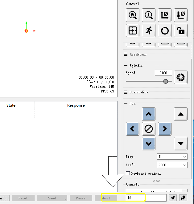
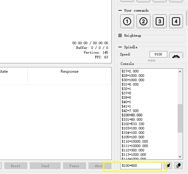
- Enter $$ in the control bar to bring up the parameter page.
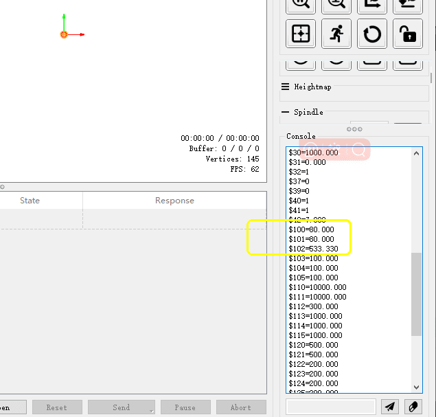
- Find the values $100, $101, and $102, and check if they are all 800.
- If any value is not 800, please change it to 800.
¶ Machine Axis Moves in the Opposite Direction, How to Handle?
- Successfully connect the software and the machine.
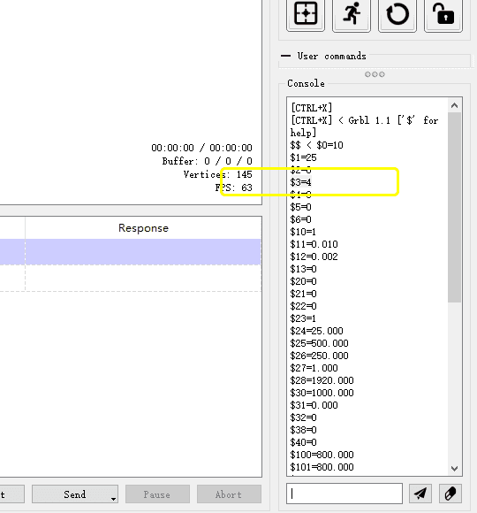
- Enter $$ in the control bar to bring up the parameter page.
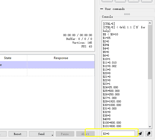
- Find the value $3 and modify it according to $3=0, $3=1, $3=2, $3=3, $3=4, $3=5.
- After each modification, check whether the direction of each axis is correct. After a maximum of 6 attempts, we can correctly modify the direction.
¶ Machine Restarts the Mainboard or Software Disconnects When Engraving?
- Mainboard firmware error, causing a large instantaneous power when the main spindle motor and stepper motor start at the same time, and the adapter power cannot keep up.
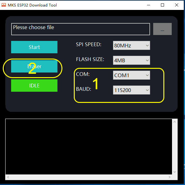
Solution: Use the flashing firmware to update the mainboard firmware again. (Please ignore the differences in the model, the writing method is the same) - Some materials have a high density, and for the machine’s main spindle, it needs to increase its speed and increase the feed amount.
¶ Motion Path is Normal, But the Drill Does Not Rotate?
- The main spindle motor line is connected correctly.
- Check if the motor line on the mainboard is plugged in properly.
- Whether the main spindle rotation is turned on in the software.
- Measure the voltage at the main spindle motor interface on the mainboard (measure when the main spindle is turned on, no voltage or insufficient voltage may indicate that the mainboard is broken).
- Test with other cables, as the cable may be damaged.
- If there is no problem with the above, it may be that the main spindle motor itself is damaged.
